Introduction
In Analog Input and Output in Arduino, we use PWM signals to control the brightness of an LED. The same idea can be applied to controlling the speed of a DC motor as well. However, since a motor draws a lot more current than an LED, and a DC motor can go in two directions, we need to build the circuit a bit differently. We can use an integrated circuit called H-bridge to help us.
In this tutorial, we will:
- understand how a H-bridge work
- control an H-bridge with Arduino
- control the speed of a motor via a H-bridge with PWM signals
To achieve the above learning outcomes, we will try controlling the speed of a small fan by a potentiometer.
Materials and Tools
- Arduino Uno x 1
- L293D H-bridge x 1
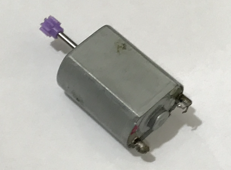
- Small DC motor x 1
- Breadboard x 1
- AA battery x 3 or 18650 battery x 1
- Battery holder
- Alligator clip wires
- Male-to-male jumper wires
- Potentiometer x 1
H-bridge
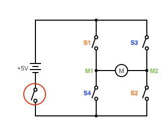
Consider the following circuit:
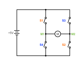
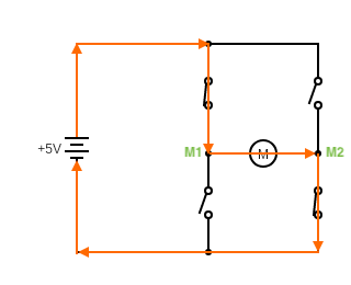
If we close S1 and S2 only, the current flows through the DC motor from M1 to M2, so the motor will move in one direction:
If we close S3 and S4 only, the current flows through the DC motor from M2 to M1, so the motor will move in the opposite direction.
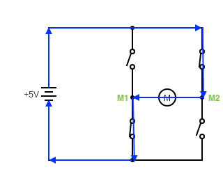
This type of circuit is called an H-bridge (since it has an ‘H’ shape). With an H-bridge, it’s easy to control the direction of rotation of a DC motor:
- When S1 and S2 are closed, the motor moves in one direction.
- When S3 and S4 are closed, the motor moves in opposite direction.
- When fewer than two switches are closed, the motor does not move, i.e. turned off.
- When more than two switches are closed, the motor does not move because of short circuit.
- When S1 and S3, or S2 and S4, are closed, the motor does not move because of short circuit.
That’s fairly simple, right? It’s all good, except it’s quite cumbersome to turn the switches on and off manually. Luckily, by using semiconductors, it is possible to make such switches very small, and control these switches like turning an LED on and off. Such circuits are often referred as integrated circuits (IC).
L293D H-bridge Integrated Circuit
The H-bridge IC we use is a cheap L293D:
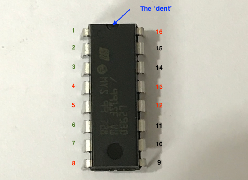
One L293D can control two motors simultaneously as long as the current does not exceed its maximum value. Let’s see how to connect the pins of L293D H-bridge to different components.
NOTE: Look at the tiny dent on the L293D IC to figure out its orientation.
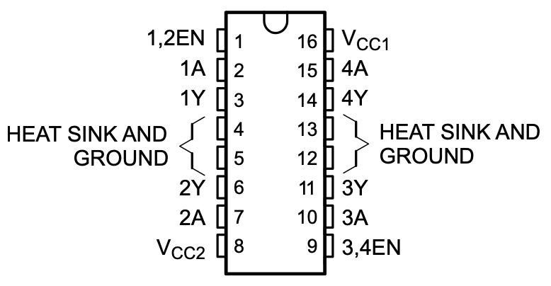
Three pins must be used in any configurations. VCC1 (pin 16) is connected to the power for the L293D (i.e. the 5V pin of the Arduino), VCC2 (pin 8) is connected to the power for the motors (i.e. the positive terminal of the battery) and Gound (pins 4, 5, 12, 13) is connected to, well, the ground. Note that you only need to connect one Ground pin to the ground.
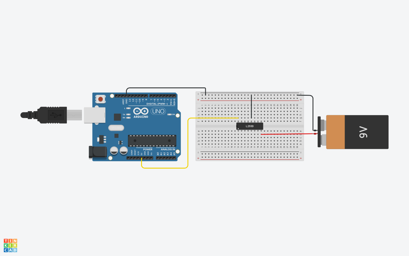
NOTE: Make sure that the ground of all components are connected. If you use a breadboard, connect the ground of the Arduino, the ground of the L293D and the negative terminal of the battery to the ground rail of a breadboard.
The remaining pins on the left, i.e. pins 1, 2, 3, 6 and 7, are for controlling one motor. The remaining pins on the right, i.e. pins 9, 10, 11, 14 and 15, are for controlling the other motor. Since we just control one motor this time, we will just use the remaining pins on the left.
Pins 3 and 6 output the voltage to the motor. They are the same as M1 and M2 in the circuit diagram.
Connect each of them to a terminal of a DC motor.
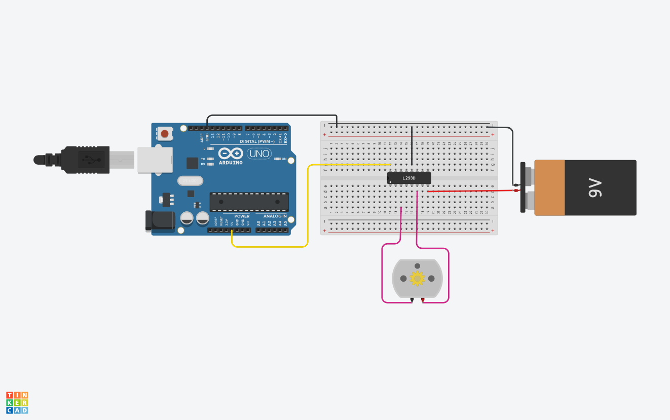
Pin 2 acts like S1 and S2 combined. When the voltage at pin 2 is 5V (HIGH), it’s the same as S1 and S2 are closed. Similarly, pin 7 acts like S3 and S4 combined. When the voltage at pin 7 is 5V (HIGH), it’s the same as S3 and S4 are closed. So, we connect make the connections to the Arduino as shown in the table below.
| L293D | Arduino |
|---|---|
| Pin 2 | Pin 12 |
| Pin 7 | Pin 13 |

Finally, imagine that we add a switch to turn on and off the entire circuit in the previous section:
We can turn the circuit on and off really conveniently. That’s what pin 1 of the L293D is. It’s called the enable pin. When the voltage at pin 1 is 5V (HIGH), it’s like the switch is closed. When the voltage at pin 1 is 0V (LOW), it’s like the switch is opened.
Remember that we can use PWM to turn on and off an LED quickly and control its brightness? The same principle can be used to control the speed of the motor. By using PWM to switch on and off the enable pin, we can control the power output, and thus the speed of the motor. So, we connect pin 1 of the L293D to pin 11 of the Arduino.
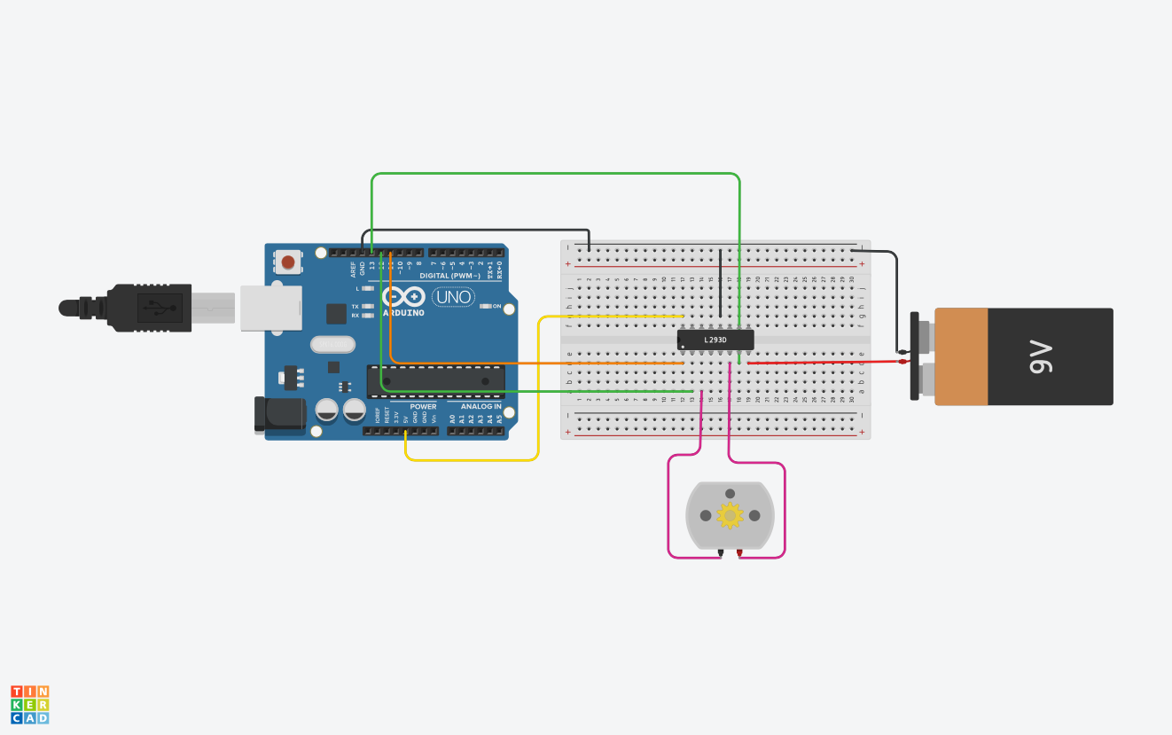
Let’s summarize how to connect the pins of the L293D:
| L293D | Connected to |
|---|---|
| Pin 1 (enable pin) | A PWM pin of Arduino (e.g. pin 11) |
| Pin 2 (first pair of switches) | A digital pin of Arduino (e.g. pin 12) |
| Pin 3 (first output) | A terminal of the DC motor |
| Pin 4/5/13/12 (ground) | Common ground of all components |
| Pin 6 (second output) | The other terminal of the DC motor |
| Pin 7 (second pair of switches) | A digital pin of Arduino (e.g. pin 13) |
| Pin 8 (power for the motor) | positive terminal of the battery |
| Pin 16 (power for the L293D) | The 5V pin of the Arduino |
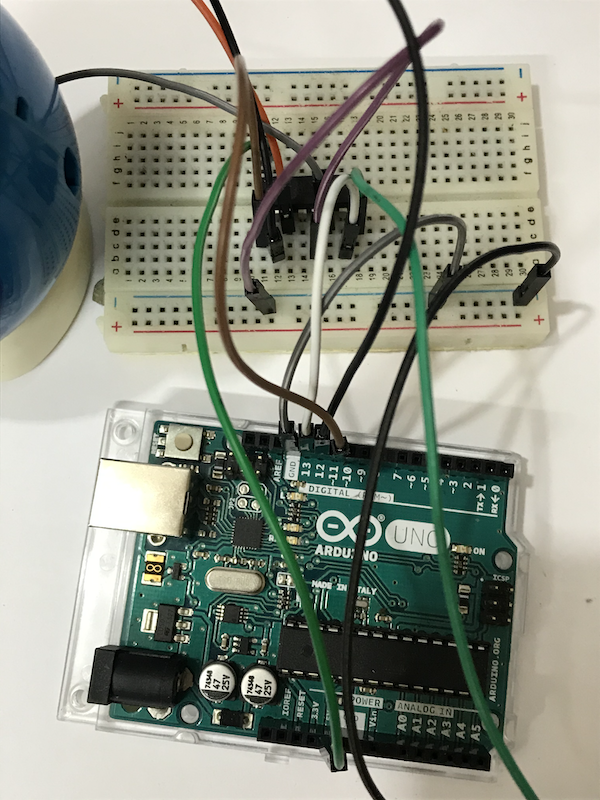
This is certainly one of the most complicated circuits for novices. However, if you understand the principle of H-bridge, you should be enable to make the correct connections. If you face any difficulties, you can always ask us via our Facebook page!
The Arduino program
Since we already know how to use the digitalWrite function and the analogWrite function in Arduino, the program is very straightforward. Let’s write a simple program to control the motor.
const int switch_1_and_2 = 12;
const int switch_3_and_4 = 13;
const int enable = 11;

void setup(){
    pinMode(switch_1_and_2, OUTPUT);
    pinMode(switch_3_and_4, OUTPUT);
    pinMode(enable, OUTPUT);
}

void loop(){
    digitalWrite(switch_1_and_2, HIGH);
    digitalWrite(switch_3_and_4, LOW);
    analogWrite(enable, 255);
    delay(2000);

    digitalWrite(switch_1_and_2, LOW);
    digitalWrite(switch_3_and_4, LOW);
    delay(1000);

    digitalWrite(switch_1_and_2, LOW);
    digitalWrite(switch_3_and_4, HIGH);
    analogWrite(enable, 255);
    delay(2000);

    digitalWrite(switch_1_and_2, LOW);
    digitalWrite(switch_3_and_4, LOW);
    delay(1000);
}
Upload the program to the Arduino, and the motor should start moving.
First, we define a few integer constants for the pins:
const int switch_1_and_2 = 12; // The first digital input
const int switch_3_and_4 = 13; // The second digital input
const int enable = 11; // The PWM input
This is a good habit, especially when we need to use quite a number of pins in the same project. It’s much easier for us to change the pins used later, and others can read your codes more easily.
Then, we do the usual configuration in the setup function:
    pinMode(switch_1_and_2, OUTPUT);
    pinMode(switch_3_and_4, OUTPUT);
    pinMode(enable, OUTPUT);
In the loop function, we first set pin 12 (switch_1_and_2) to HIGH and pin 13 (switch_3_and_4) to LOW.
    digitalWrite(switch_1_and_2, HIGH);
    digitalWrite(switch_3_and_4, LOW);
We This is the same as closing switches 1 and 2 and keeping switches 3 and 4 opened:
Then we use the analogWrite function to set the duty of the PWM signal for the enable pin:
    analogWrite(enable, 255);
    delay(2000);
We set the duty to 255 this time, so the motor moves in one direction in full power for 2 seconds.
NOTE: If the duty is lower than a certain value, the motor may not move at all, since the motor needs a particular amount of power to have enough torque.
Then, we switch off the motor for 1 second by setting both pins 12 and 13 to LOW.
    digitalWrite(switch_1_and_2, LOW);
    digitalWrite(switch_3_and_4, LOW);
    delay(1000);
NOTE: Alternatively, you can turn off the motor by setting the enable pin to
LOW.
Next, we set pin 12 (switch_1_and_2) to LOW and pin 13 (switch_3_and_4) to HIGH.
    digitalWrite(switch_1_and_2, LOW);
    digitalWrite(switch_3_and_4, HIGH);
    analogWrite(enable, 255);
    delay(2000);
This is the same as closing switches 3 and 4 and keeping switches 1 and 2 opened, so the motor changes its direction:
Finally, the motor stops for 1 second before it moves again.
You can check out the sample code when you complete the task, and ask us through Facebook if you find any difficulties.
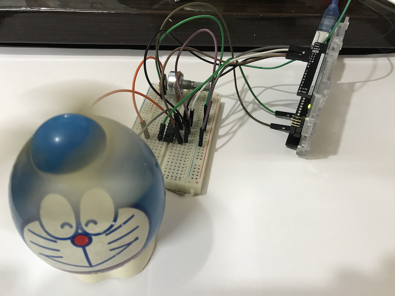
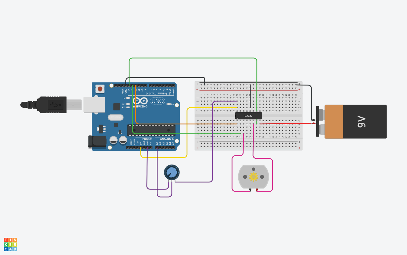
Use a Potentiometer to Control a Fan
Similar to controlling the brightness of an LED with a potentiometer, we can use a potentiometer to control the speed of a motor:
Let’s connect the potentiometer to the circuit.
You need some small modifications in the program to achieve this:
- Since we only need the motor to rotate in one direction only, the
digitalWritefunction can be called in thesetupfunction instead of theloopfunction - You need to read the value from the ADC periodically, and map the value to a duty by using the
mapfunction in Arduino
Look at the model answer here when you complete the task, and ask us through Facebook if you find any difficulties.
Conclusion and Assignment
In this tutorial, we have used Arduino to control the direction of rotation and the speed of a DC motor. This is an important step towards making a robot. In the future, you can use an Arduino-compatiable ESP8266/ESP32 chip, or even a Raspberry Pi computer, to control motors via Wifi or Bluetooth. That means you can create all sorts of motorized machines that can be controlled remotely.
To consolidate the knowledge, you may try changing the codes a bit to achieve the following results:
When the potentiometer is turned to one end, the motor moves with maximum speed in one direction; when the potentiometer is turned to the middle, the motor stops; when the potentiometer is turned to the other end, the motor moves with maximum speed in the other direction.
Look at the model answer here when you complete the task, and ask us through Facebook if you find any difficulties.