Introduction
Arduino is an excellent hardware and software platform for entering the world of physical computing. By using a microcontroller (which is essentially a small, cheap and simpler computer) and the Arduino IDE, you can do a lot of amazing things by yourself.
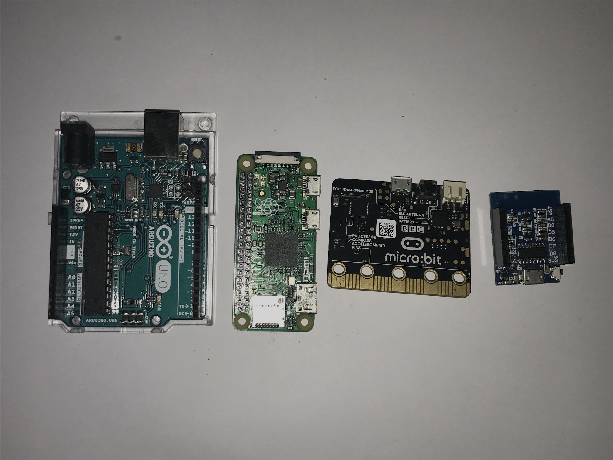
Since both the hardware and the software of Arduino are open source, different manufacturers can make their microcontrollers compatiable with the Arduino IDE. From the cheap Arduino clones from China to the popular BBC micro:bit, Arduino IDE can be used to write and upload programs.
In this tutorial, we will:
- explore what GPIO is,
- understand the basic structure of an Arduino program,
- control a digital output with an Arduino program,
- process a simple digital signal with an Arduino program,
- control a digital output with a digital signal through an Arduino program.
To achieve the above learning outcomes, we will try controlling an LED light by connecting and disconnecting a wire.
Although the artifact itself is trivial, this project is conceptually important. Once you master all the concepts in this tutorial, you can build a wide variety of projects by yourself.
Materials and Tools
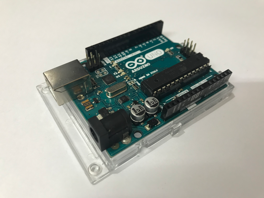
- Arduino Uno x 1
- LED x 1
- Male-to-male breadboard jumper x 1
- A computer with Arduino IDE installed
- A USB-A type cable for connecting the Arduino Uno to a computer
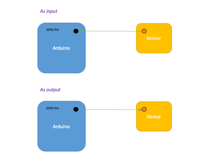
1. What is GPIO?
You’ve probably seen the term GPIO somewhere, but what exactly is it? GPIO stands for General Purpuse Input Output. In short, you can use a GPIO pin as an input or as an output by writing suitable programs. That means we can use a GPIO pin to read signals from things like buttons, switches and sensors, or to send signals to other devices such as LEDs and motors to control these devices.
Popular platforms like Arduino, Raspberry Pi, micro:bit and ESP8266/ESP32 all have GPIOs. Makers can have excellent control over how these pins behave, and therefore they can create projects that go beyond our imagination.
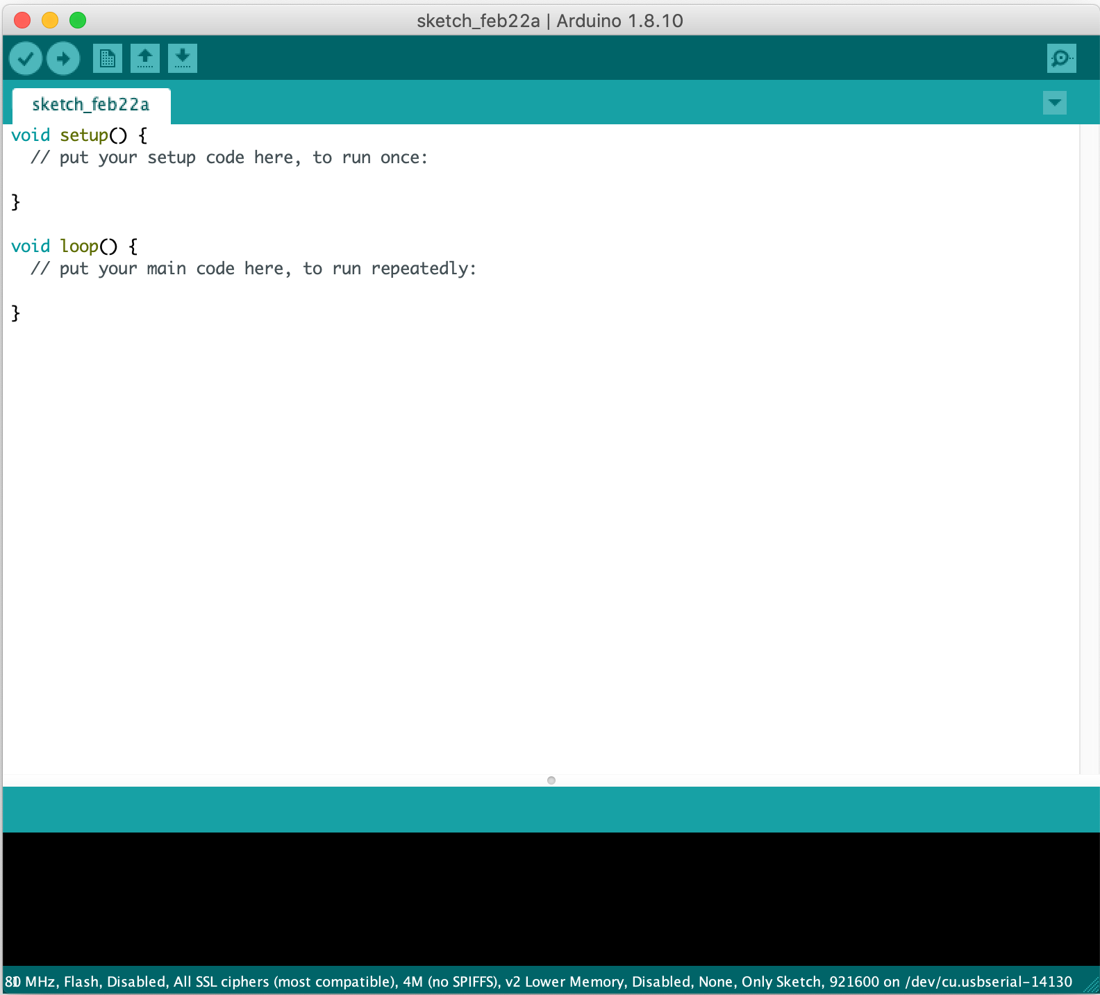
2. The basic structure of an Arduino program
It is time to start the Arduino IDE. A new stekch should be created automatically once it is started. Alternatively, you can always create a new sketch by clicking File → New.
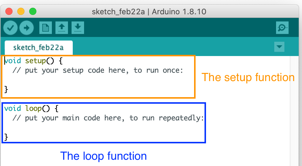
A program is a set of instructions for a computer to perform specific tasks. We often group a bunch of related instructions into a function. When a function is called, the instructions inside the function are executed. There are two basic functions in every Arduino program:
- The
setupfunction, which is called once when the board is turned on. - The
loopfunction, which is called repeatedly indefinitely after thesetupfunction is executed.
3. Turn on and off an LED light programmatically
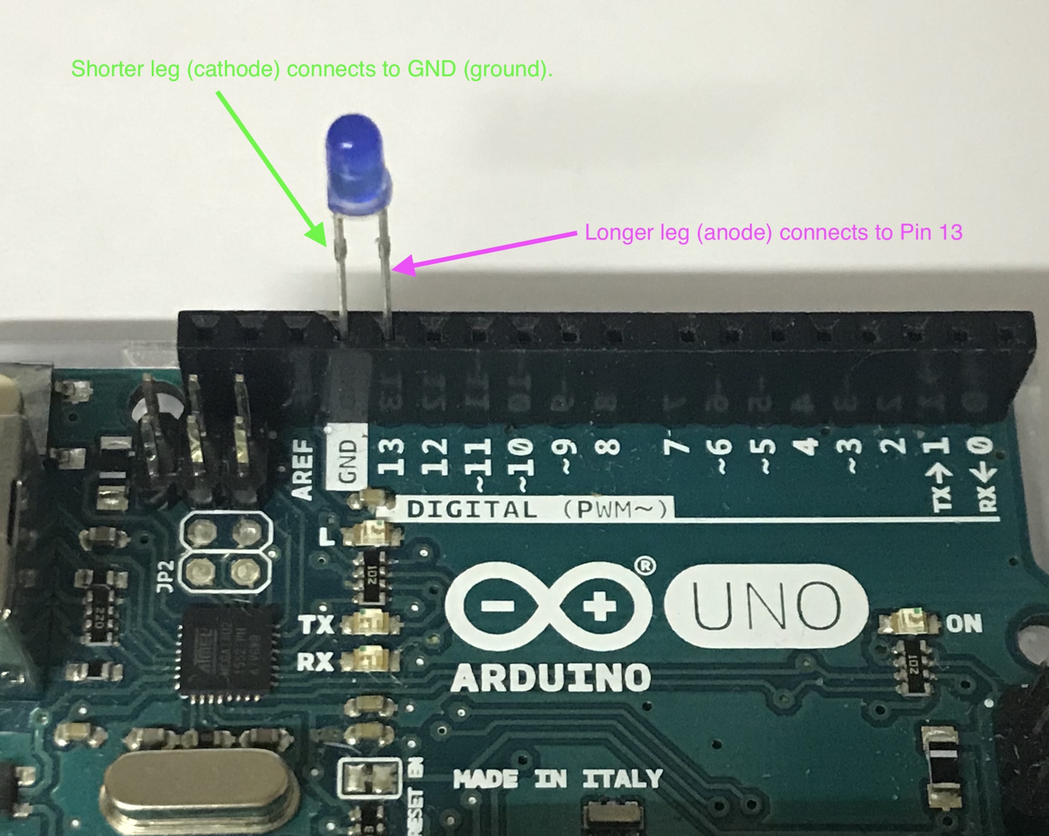
Let’s control a LED programatically. We will use Pin 13 of the Arduino board to control the LED directly. This pin is chosen as it has a built-in resistor protecting the LED from large current, and so we don’t need to add an extra resistor. Connect the LED in the following way:
To set Pin 13 to output mode, we call the pinMode function inside the setup function.
void setup() {
  pinMode(13, OUTPUT);
}
The values inside the parentheses are arguments passing to the function pinMode. Functions can execute its instructions depending on the values of the arguments. We will cover this topic much deeply later.
Then, let’s write the codes inside the loop function to make the LED blinking at a regular time interval.
void loop() {
    digitalWrite(13, HIGH);
    delay(1000);
    digitalWrite(13, LOW);
    delay(1000);
}
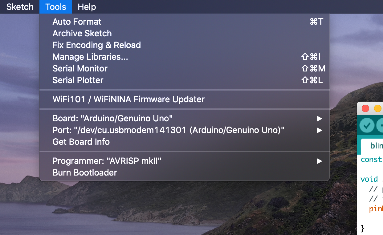
That’s quite a lot of codes, isn’t it? But why not upload the sketch to the Arduino board and see what happen first? Connect the Arduino to the computer. In the Arduino IDE menu, click:
- Tools → Board → Arduino/Genuino Uno
- Tools → Port → the port used by the Arduino Uno
- Tools → Programmer → AVRISP mkII
After that, click the ‘upload’ button:
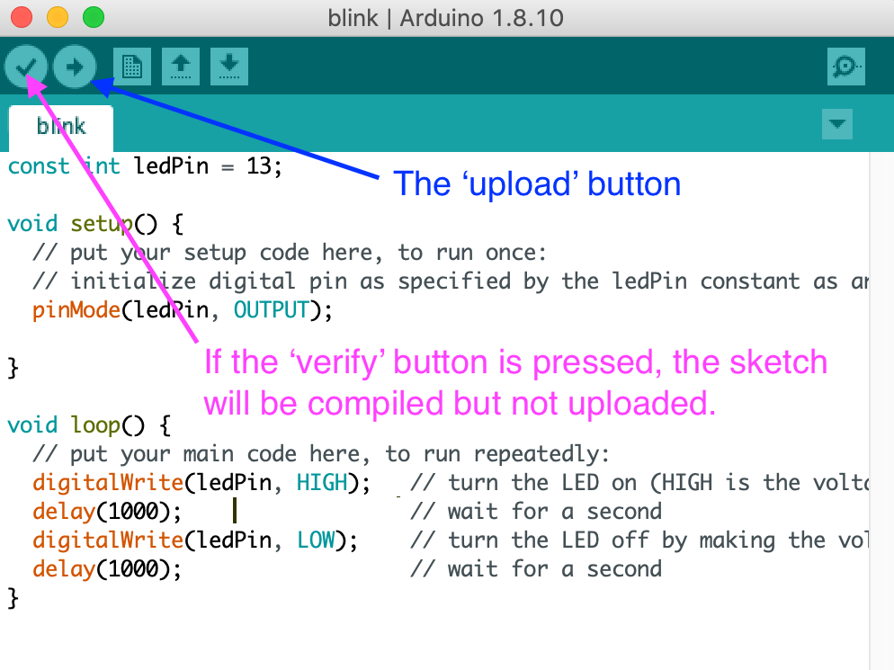
If everything is done correctly, you should be able to see the LED blinking!
But if things really go wrong, don’t worry! Programmers spend a lot of time on debugging (fixing errors). You can find the code in this repository. Check carefully (and patiently) what possible errors have been made. If all else fail, you can ask us through our Facebook page!.
Let’s look at the setup and the loop functions in details.
In the setup function:
  pinMode(13, OUTPUT);
  // The pinMode function with the OUTPUT as the second argument set the voltage at pin 13 to 0 V.
  // By the way, comments in an Arduino sketch starts with //.
  // Comments are ignored by the compiler, and they are notes for programmers only
When the pinMode function is called with a constant OUTPUT as the second argument, the voltage at Pin 13 is 0 V, so the LED is turned off.
In the loop function:
  digitalWrite(13, HIGH);
  delay(1000);
When the digitalWrite function is called with a constant HIGH as the second argument, the voltage at Pin 13 is 5V, so the LED is turned on. Then, the delay function with 1000 as the argument pauses the program for 1000 milliseconds (i.e. 1 second), therefore the LED remains on for 1 second.
  digitalWrite(13, LOW);
  delay(1000);
After pausing the program for 1 second, the digitalWrite function is called again with a constant LOW as the second argument, the voltage at Pin 13 is 0 V, so the LED is turned off. The delay function keeps the LED off for another second.
Since the loop function runs repeatedly indefinitely, the LED is blinking all the time!
4. A simple digital input
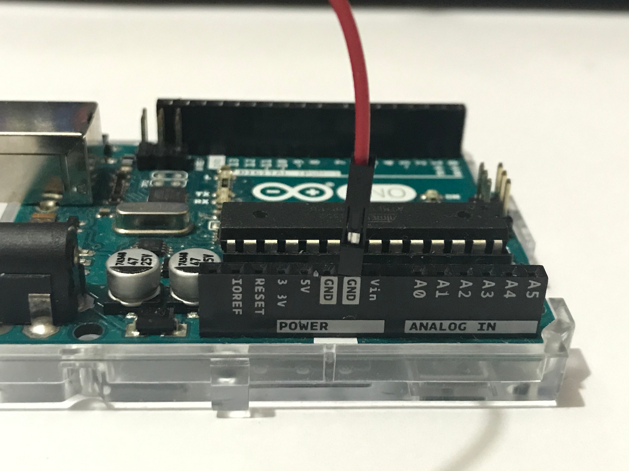
In this practice, we will write a simple program to read a digital signal. But first, remove the LED from the Arduino board, and connect a male-to-male breadboard jumper to a GND pin.
Then, open a new sketch in the Arduino IDE. Write the setup function as follows:
void setup(){
    pinMode(2, INPUT_PULLUP);
    Serial.begin(9600);
}
Then, let’s write the codes inside the loop function to read the signal at Pin 2.
void loop(){
    int pin_state = digitalRead(2);

    if (pin_state == LOW){
        Serial.println("Cable inserted!");
    }
}
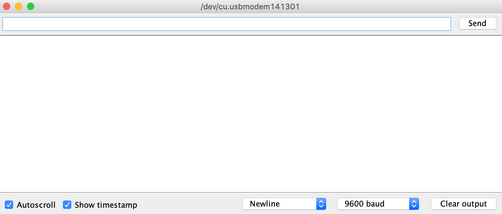
Go ahead and upload the sketch to the Arduino board. Then, in the menu, click Tools → Serial Monitor to open the Serial Monitor. Tick the two checkboxes ‘Auto scroll’ and ‘Show timestamp’, and select ‘Newline’ and ‘9600 buad’ in the two dropdown menus.
Now, plug in the other end of the breadboard jumper to Pin 2 and pull it out repeatedly.
The Serial Monitor should show new lines of texts whenever the breadboard jumper is in Pin 2.
Let’s look at the the setup and the loop functions in details.
In the first line of code inside the setup function:
pinMode(2, INPUT_PULLUP);
We first set Pin 2 to input mode with the INPUT_PULLUP constant as the second parameter. We will use Pin 2 as an input pin. When the pinMode function is called with a INPUT_PULLUP as the second argument, the voltage at Pin 2 is 5 V when nothing is connected to it.
NOTE: There is another constant
INPUTthat can be used as the second argument, but we will need to add a pull down resistor to make things work probably. We will deal with this in a more advanced tutorial.
In the second line of code inside the setup function:
Serial.begin(9600);
To facilitate debugging, the Arduino IDE has a built in Serial Monitor. It allows the Arduino board to communicate with the computer it connects to. The line of code Serial.begin(9600); enables this function, and the argument 9600 is the baud rate. For now, you don’t need to worry about it. All you need to do is to ensure that this baud rate is the same as the one selected in the Serial Monitor.
In the loop function:
int pin_state = digitalRead(2);
The digitalRead function is called first to read the state of Pin 2 and store the state to the integer variable pin_state. If the voltage at Pin 2 is 5V, digitalRead returns a constant HIGH; otherwise, it returns a constant LOW.
In the next part:
    if (pin_state == LOW){
        Serial.println("Cable inserted!");
    }
This is an if statement. pin_state == LOW is a condition asking whether the value of pin_state equals the value of the constant LOW. If it is true, then the statements in the parentheses following the condition will be executed.
NOTE: The
==operator compares the values of the two sides. If they are equal, the booleantruewill be returned; otherwise,falsewill be returned. A similar operator!=, which means ‘not equal to’, works in the exact opposite way.
Let’s look back a bit: when will the value of pin_state be LOW? When the jumper is plugged into Pin 2! Why? The other side of the jumper is connected to the ground (GND), i.e. at 0 V. When GND and Pin 2 are connected, the voltage at Pin 2 becomes 0 V, and hence digitalRead(2) will return LOW.
One more note on this activity: plugging in and pulling out a jumper cable is a cumbersome task. Can we just use a button for this? Yes, we can, and we probably should. The above is the basic working principle of pretty much all buttons inside digital devices.
In case you find any difficulties, check out the model answer here.
5. Control a digital output with a digital signal through an Arduino program
It is time to consolidate the knowledge by making an artifact. Here’s the requirements for the artifact:
When we plug the jumper into Pin 2, the LED at Pin 13 will be turned on; otherwise, it is turned off.
Actually, you have almost learnt everything you need to make this. Let’s look at the if statement in the sketch for the previous section:
    if (pin_state == LOW){
        Serial.println("Cable inserted!");
    }
In fact, we can add an ‘else’ block that will be executed when the value of pin_state is not LOW:
    if (pin_state == LOW){
        Serial.println("Cable inserted!");
    } else {
        // The codes inside this pair of parentheses will be executed if `pin_state == LOW` returns `false`
        Serial.println("Cable unplugged!");
    }
With this new piece of information, try piecing all the things together to solve the given problem. Look at the model answer here when you complete the task, and ask us through Facebook if you find any difficulties.
6. Conclusion and assignment
Let’s look back what we have done in this activity: a. Use an Arduino program to turn on and turn off a digital device b. Use an Arduino program to process signals from a digital device c. Mixing (a) and (b) to create other projects
Many Arduino projects are pretty much based on these three things. Consolidate your knowledge further by completing the following assignment:
When we plug the jumper into Pin 2, the LED at Pin 13 will be flashing; otherwise, it is turned off.
You may find the solution here.