Introduction
In the tutorial Arduino for Absolute Beginners, we plug the LED and the cableinto the Arduino directly. While this method works in that simple project (with the minimal amount of materials and tools), it’s not a practical way to build more complicated circuits. For instance, if you want to connect four devices (sensors or actuators) to the Arduino, and all of them need to be connected to the ground (i.e. the GND pins), then it will be impossible to plug all the things into the Arduino, since there are only 3 GND pins. With a breadboard, this problem is solved.
In this tutorial, we will:
- understand how to use a breadboard,
- construct a circuit with a breadboard.
To achieve the above learning outcomes, we will rebuild the circuit in Arduino for Absolute Beginners properly with a breadboard.
Materials and Tools
- Arduino Uno x 1
- Breadboard x 1
- LED x 1
- Tactile button x 1
- Male-to-male breadboard jumpers x 5
Choose a Breadboard
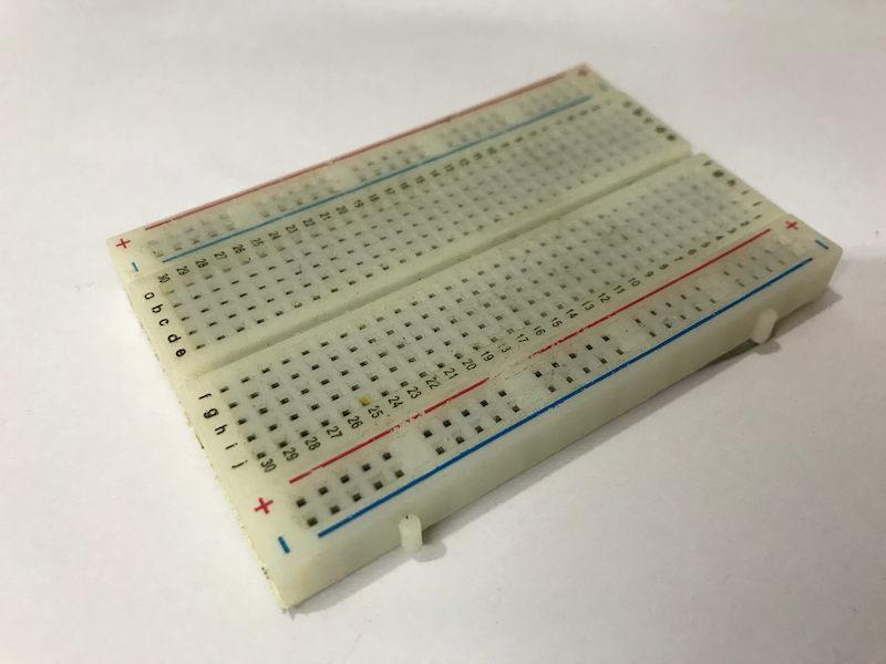
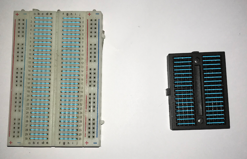
These are two common types of breadboards, and they are pretty much the same, except the bigger one has the power and the ground rails:
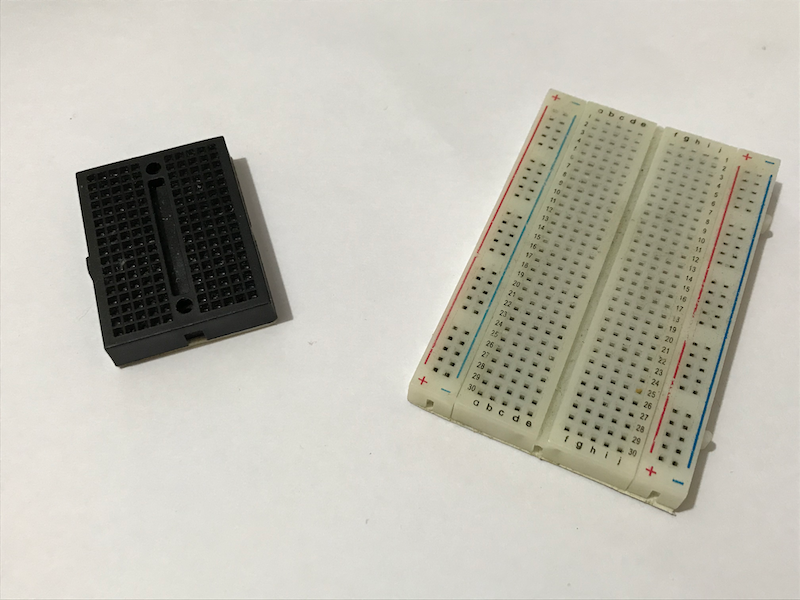
The following are some criteria that you may consider when you choose a breadboard:
- How complex is your circuit?
- How many power and ground pins do you need?
- How compact is your project?
- Do you need to chain multiple breadboards together?
Rows on a Breadboard
Regardless of which types of breadboards, the holes in each row are connected to a same piece of conductive material. In order words, the holes in the same row have the same electric potential. Connecting two things to two holes in the same row is the same as connecting these two things by a wire.
Power and Ground Rails
If you use a larger breadboard, you can also see two extra columns (rails) at each side of the breadboard. The holes in each rail are connected to the same piece of conductive material. Therefore, connecting two things two holes in the same rail is the same as connecting these two things by a wire.
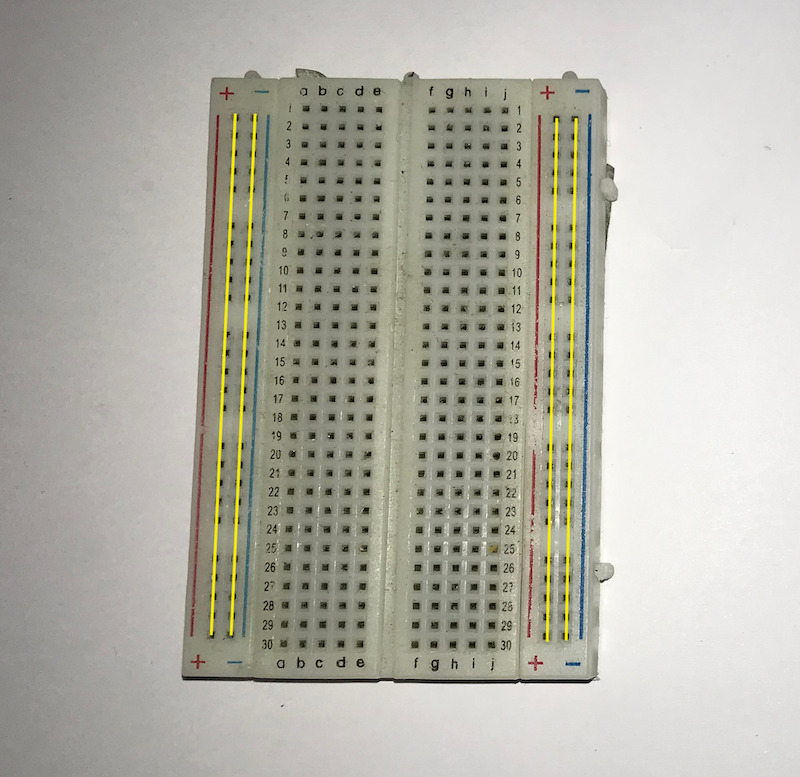
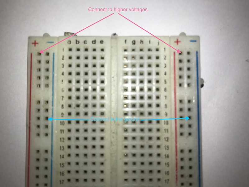
On each side, one rail is indicated by a red line and the other is indicated by a blue line. The “red rail” is usually for higher voltage (either from the microcontroller or an external power source like batteries) and the “blue rail” is usually for the ground. You don’t need to follow this, but doing so may confuse yourself. So, it’s better to just use these rails as indicated.
Construct a Circuit with a Breadboard
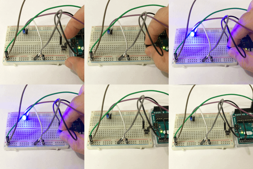
If we construct the same circuit as in Arduino for Absolute Beginners with a breadboard, it will look something like this:
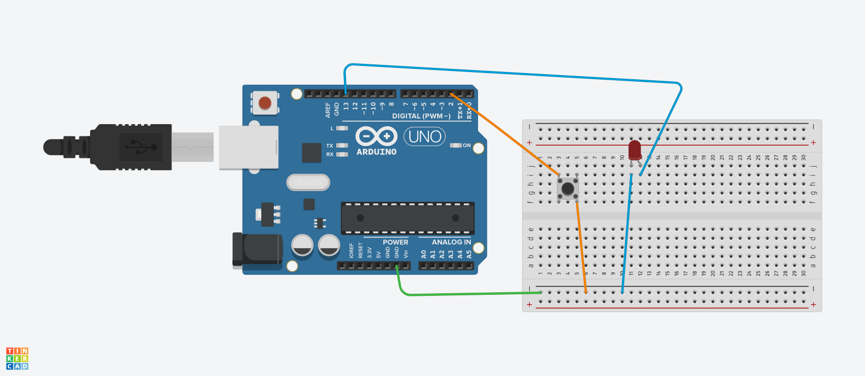
Let’s construct the circuit step-by-step.
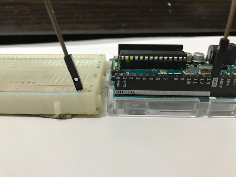
A. Connect Arduino’s GND to the ground rail
Connect a GND pin of the Arduino to a ground rail. Then, we can connect the GND pin of each components to the ground rail rather than the three GND pins of Arduino.
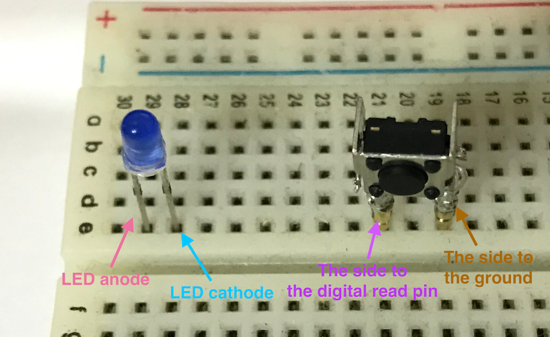
B. Connect the LED and the button
Connect the LED and the button to the breadboard such that each leg occupies a new row.
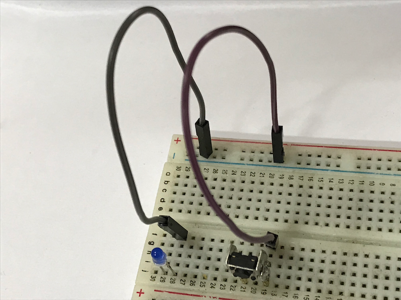
C. Connect the components to the ground rail
Connect the rows where the LED’s cathode and one side of the button are located to the ground rail.
D. Connect LED’s ancode to the Arduino
Connect the row where the LED’s anode is located to Pin 13 of the Arduino.
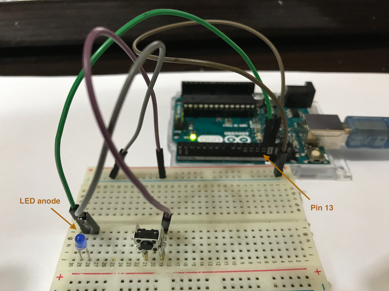
E. Connect the other side of the button to the Arduino
Connect the row where the other side of the button is located to Pin 2 of the Arduino.
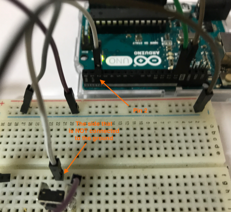
F. Upload the code
Finally, connect the Arduino to the computer and upload the code for the last assignment. Press the button and see if the LED flashes!
If you find any difficulties, don’t forget to ask us through our Facebook page!.
Conclusion and Assignment
Let’s look back at this activity. We use a breadboard to help us construct a circuit. This may look over-complicated at first, but you will find using breadboards very essential at the prototyping stage when making your project. There’s no better way to demonstrate this to you by asking you to do the following assignment:
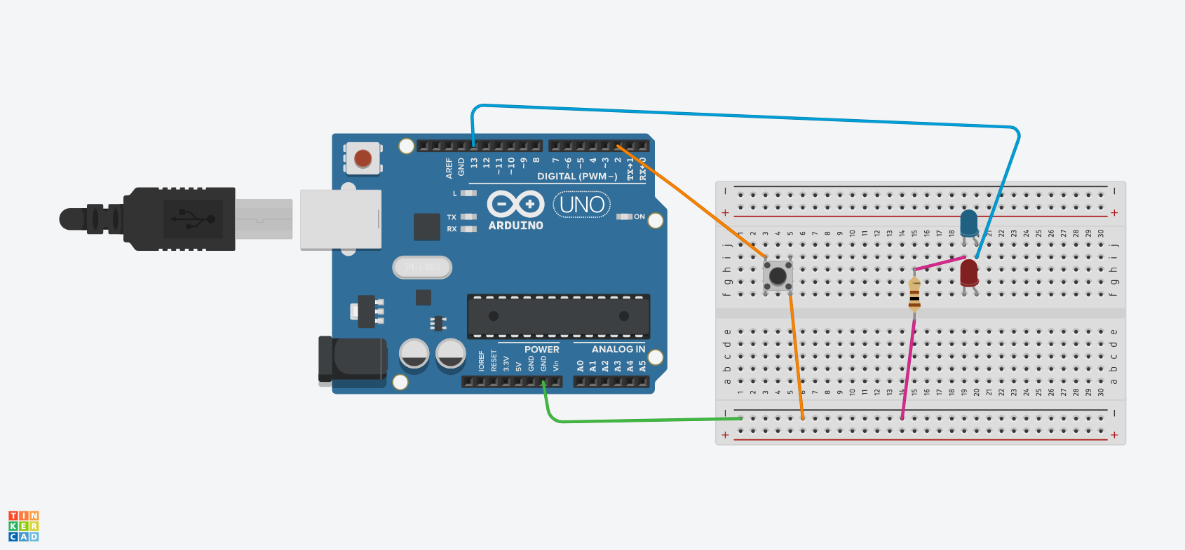
Modify the circuit such that two LEDs flash when the button is pressed. In addition, one resistor is add to protect the LEDs from large current.
Use the following circuit diagram as reference:
