Introduction
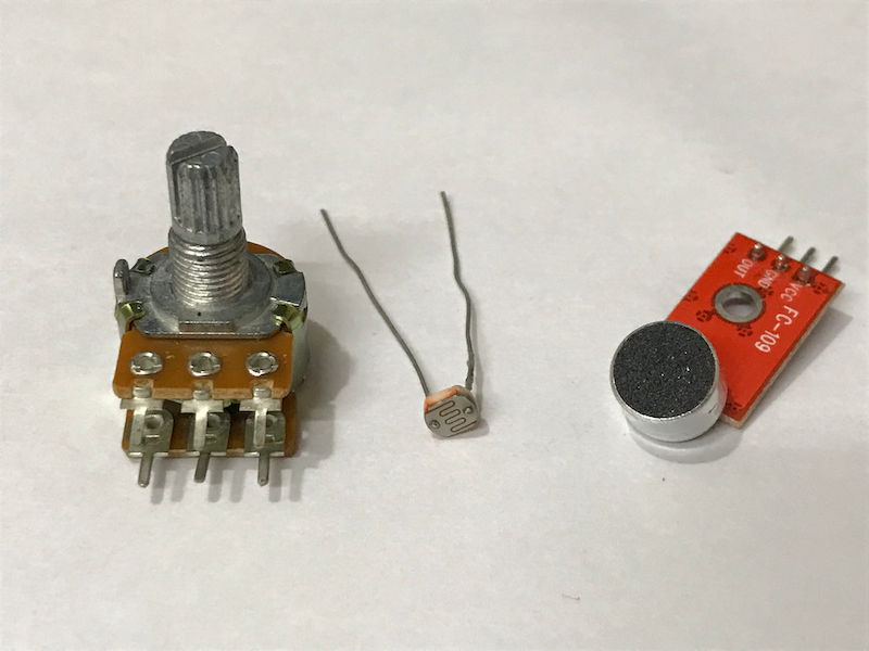
In Arduino for Absolute Beginners and Using a Hall Sensor in Arduino, we have explored how to use Arduino to process digital signals and control other devices digitally. However, there are situations that binary signals (0 and 1, or LOW and HIGH) are not enough. For example, we cannot do the following things with just binary signals:
- Adjust the volume of a speaker continuously by turning a knob
- Adjust the brightness of a lamp continuously when the ambient light level changes
- Adjust the speed of a motor continuously by varying how deep the accelerator is pressed
In these situations, the variables are changing continuously. Continuous signals that change with time are called analog signals. Arduino can process analog signal with its built-in analog-to-digital converter (ADC). However, it cannot produce real analog signals, as it lacks a digital-to-analog converter (DAC). Of course, we can add an external DAC to the Arduino, but we usually don’t need to do so. In most of the cases, a technique called pulse-width modulation (PWM) is enough for controlling the average power delivered by an electrical signal.
In this tutorial, we will:
- process an analog signal with an Arduino program,
- control a PWM output with an Arduino program,
- control a PWM output with an analog signal through an Arduino program.
To achieve the above learning outcomes, we will try controlling the brightness of an LED light by a potentiometer.
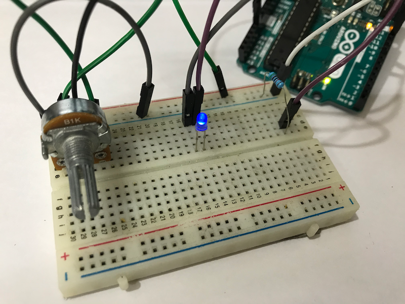
Again, the artifact itself may look trivial, this project is conceptually important. Together with digital input and output, you can build a wide variety of projects by yourself.
Materials and Tools
- Arduino Uno x 1
- LED x 1
- Potentiometer x 1
- 10 ohm resistor x 1
- Male-to-male breadboard jumper x 7
Introducing the ADC
As mentioned, the Arduino has a built-in ADC. Essentially, this ADC measures the voltage at a pin, and map the measured value to an integer from 0 to 1023 linearly, i.e.

NOTE: The maximum voltage that the Arduino can measure is 5V. Beyond that, the Arduino can be damaged.
The ADC can read one value at a time. However, if we read the value of a pin repeatedly very quickly (e.g. call the reading function is the loop function), then we can construct an analog graph that looks almost continuous.
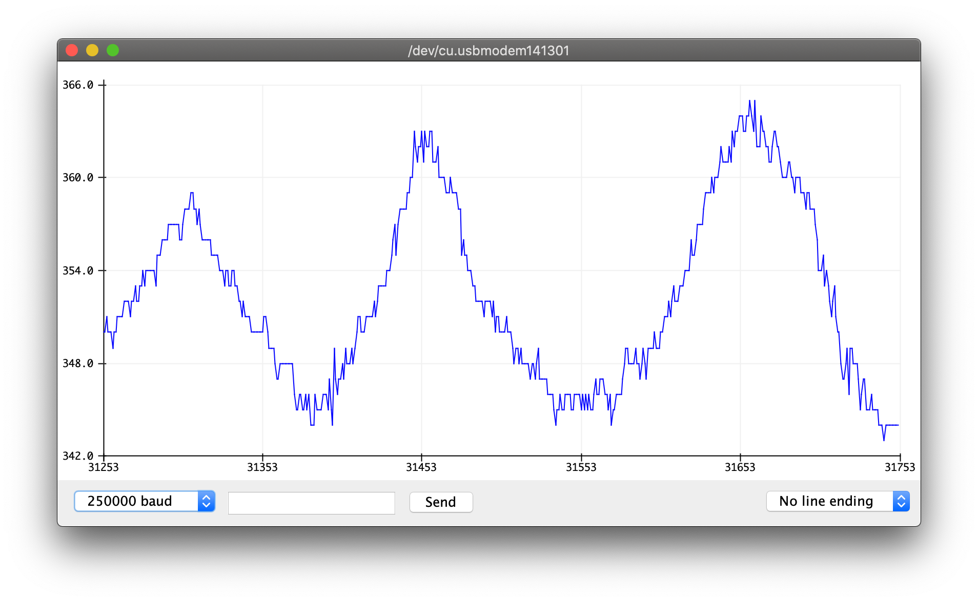
How fast an ADC reads a new value is often referred as the sample rate. We can reproduce the analog signals more accurately with a higher sample rate. For example, the sample rate of telephone audio is about 8 kHz, while the sample rate of lossless audio is about 40 kHz.
Read how much a potentiometer is turned in Arduino
By using a variable resistor, we can change the voltage measured at a point in a circuit. For example, in the following circuit, if we change the resistance of the variable resistor when we measure the voltage at a point between the variable resistor and a fixed resistor, we can get different values.
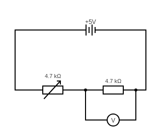
This time, we use a three-leg potentiometer, which has a variable resistor and a fixed resistor. The middle leg is connected to a point between the variable resistor and the fixed resistor.
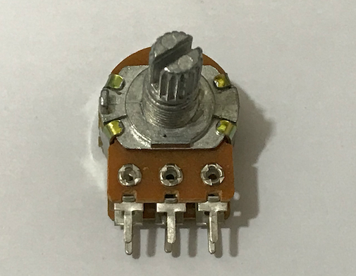
Let’s connect the potentiometer to the Arduino and see what we can get. Connect the three legs of the potentiometer as below:
| Potentiometer | Arduino |
|---|---|
| Left leg | 5V |
| Middle leg | A0 |
| Right leg | GND |
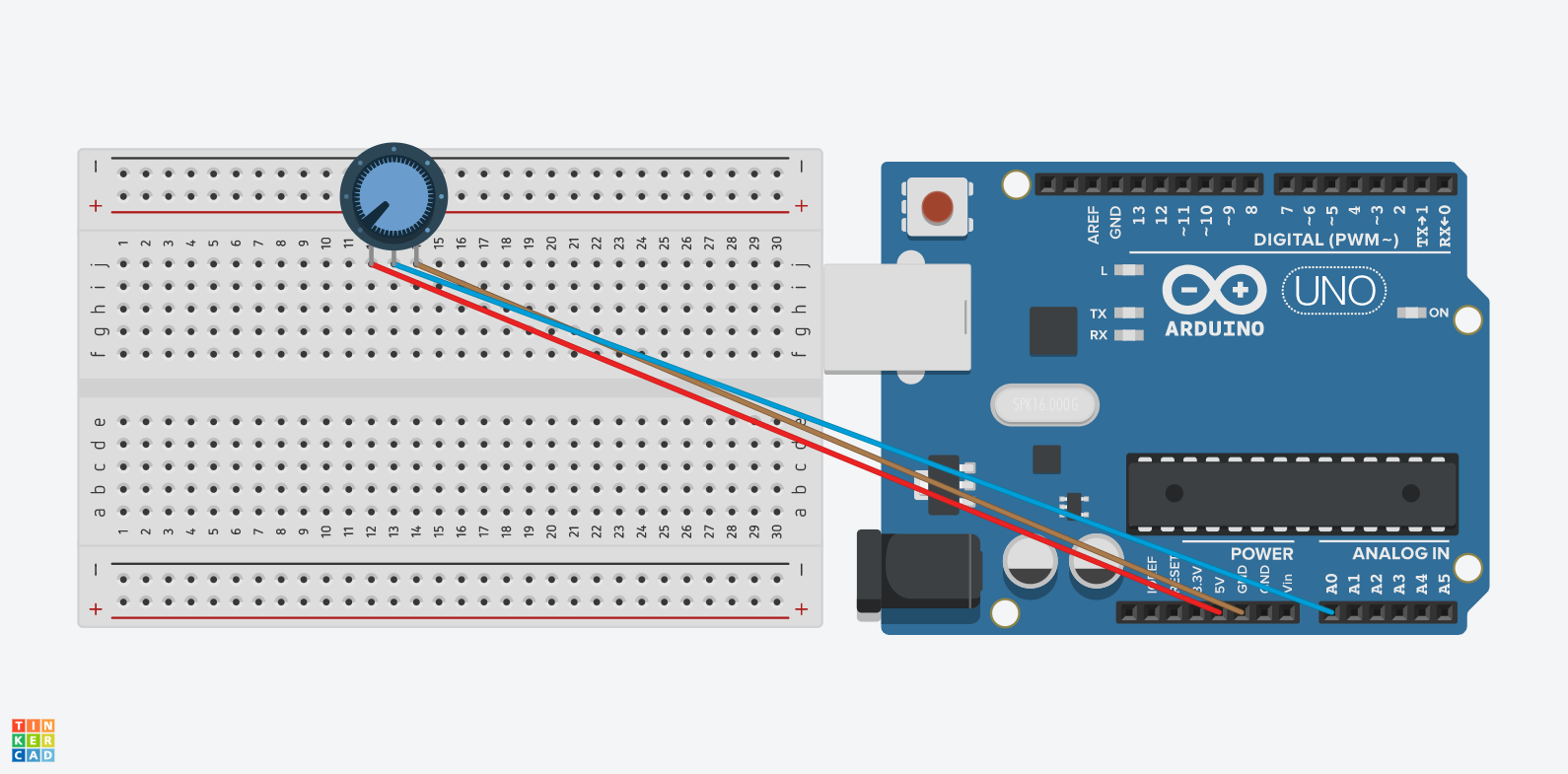
You may wonder which one is the left leg (or the right leg). As you will see later, it doesn’t really matter.
Then, lets’s write the Arduino program.
void setup(){
    pinMode(A0, INPUT);
    Serial.begin(9600);
}

void loop(){
    int analog_value = analogRead(A0);
    Serial.println(analog_value);
    delay(100);
}
Go ahead and upload the program to the Arduino. After uploading the code, click ‘Tools’ → ‘Serial Plotter’ and rotate the potentiometer.
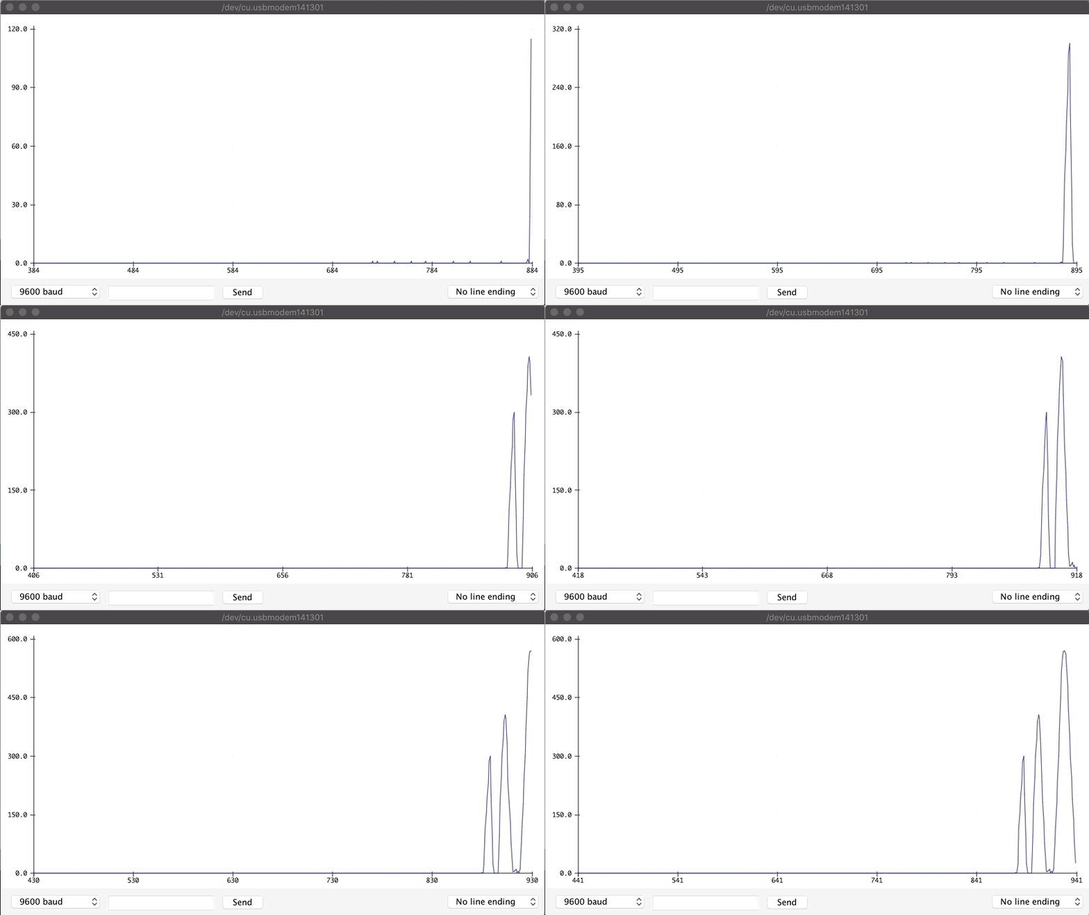
When the knob is rotated in clockwise, the value increases; otherwise, the value decreases. You may see the opposite result. In this case, you can just swap the connections of 5V and GND. That’s why which one is the left or the right leg does not matter - you can test it yourself, and configure the circuit as you like.
Let’s look at the codes in details.
The setup function looks almost the same as before. We use pinMode(A0, INPUT) to set the A1 pin to input mode.
NOTE: In the Arduino, only pins A0 to A5 can be used for analog input. Moreover, these 6 pins can be used as a digital output.
In the loop function, we call analogRead to read the output value of the A0 pin. As shown in the previous formula, the minimum and the maximum output values are 0 and 1023 respectively. delay(100) pauses the program for 0.1s, so analogRead is called about 10 times in a second. Thus, the sample rate is about 10 Hz.
Look at the model answer here when you complete the task, and ask us through Facebook if you find any difficulties.
Control the brightness of an LED with PWM
At home, we usually adjust the brightness of a light bulb with a physical knob. Traditionally, a potential divider is used to achieve this (see the circuit diagram of a potential divider in the last section). However, what if you want to control the brightness of the light bulb programatically, say, via your smartphone? This is one of the examples of Internet of Things (IoTs). It turns out that it’s quite easy to control the brightness of an LED with Pulse Width Modulation (PWM) signal.
PWM is essentially switching on and off the power very rapidly at a particular frequency. By varying the amount of ‘on’ time and ‘off’ time in the period of each cycle, we can control the average power output. The proportion of ‘on’ time to the period of each cycle is known as the duty cycle. 25% duty cycle means that the power is on for 25% of the time in each cycle, 50% duty cycle means that the power is on for 50% of the time in each cycle.
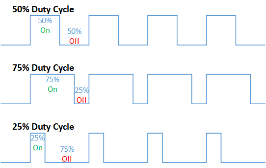
In other words, if we want to reduce the power output by 50%, we can set the duty cycle to 50%.
NOTE: The digital signals
HIGHandLOWcan be seen as 100% and 0% duty cycles respectively.
In Arduino UNO, the pins 3, 5, 6, 9, 10, 11 can generate high frequency PWM wave. Pins 3, 9, 10 and 11 generate PWM wave of 490 Hz, while pins 5 and 6 generate PWM wave of 980 Hz.
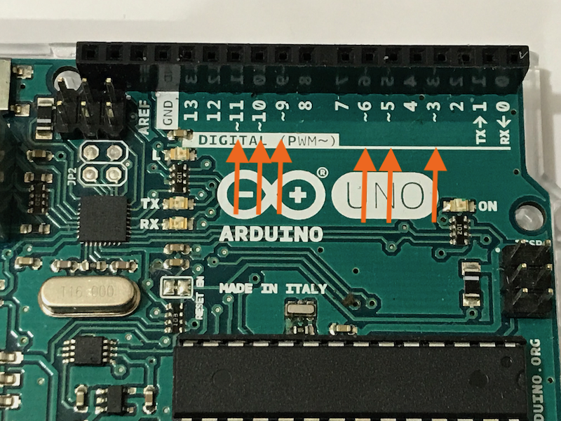
NOTE: These pins can generate higher frequency PWM wave. However, if you only need a lower frequency of PWM wave, you can create your own PWM wave by setting a digital pin
HIGHandLOWin particular intervals of time. This method is known as ‘bit-banging’.
Let’s connect an LED to the Arduino according to the following circuit diagram.
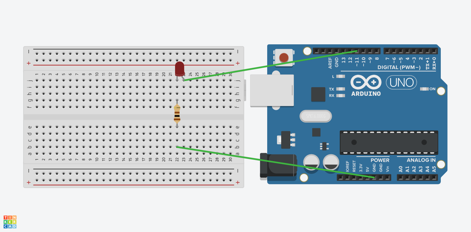
Then, let’s write the Arduino program.
void setup(){
    pinMode(11, OUTPUT);
}

void loop(){
    int duty = 0;
    for (duty = 0; duty < 256; duty++){
        analogWrite(11, duty);
        delay(20);
    }
}
Upload the program to the Arduino, and you should see the brightness of the LED increases gradually.
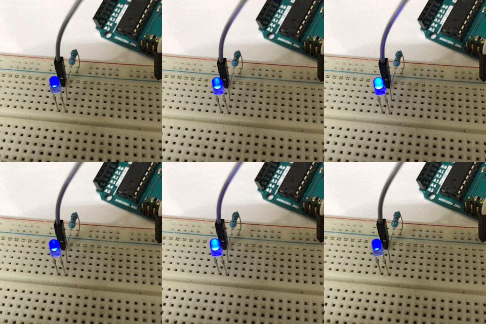
Let’s look at the code in details. The setup function is the usual one. We simply set pin 11 to output mode by calling the pinMode function with arguments 11 and OUTPUT.
In the loop function, we first declare an integer variable called duty, and initialize it as 0:
int duty = 0
Then, we use a for loop to repeatedly do something:
    for (duty = 0; duty < 256; duty++){
        analogWrite(11, duty);
        delay(20);
    }
Inside the for loop, we call the analogWrite function to change the duty cycle of the PWM output of pin 11, then pause the program for 20 milliseconds, and finally the value of duty is increased by 1. The loop will stop when the value of duty reaches 256.
The first argument of analogWrite is the pin number, and the second argument is the duty cycle value. The range for the duty cycle value is from 0 to 255. Thus, if you want to set the duty cycle to a particular percentage, just multiply this percentage with 255, and you will get the value for the analogWrite function.
Look at the model answer here when you complete the task, and ask us through Facebook if you find any difficulties.
5. Control a PWM output with an analog signal
It is time to consolidate the knowledge by making the final artifact. Let’s use a potentiometer to control the brightness of the LED:
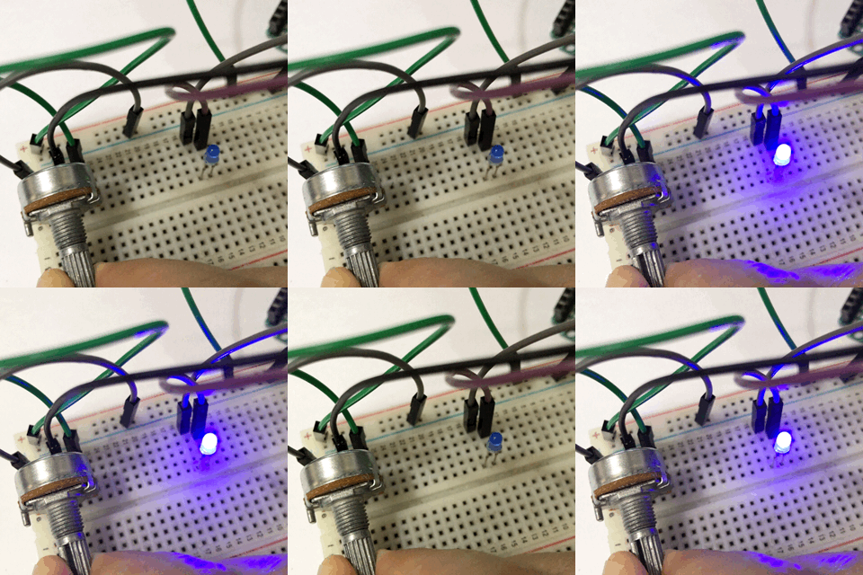
You can modify the codes in the previous sections to achieve this. The only thing that you need to pay attention to is that the analogRead gives you a value from 0 to 1023, while the analogWrite function requires a value from 0 to 255. Thus, you may need the map function to help you:
map(value, from_min, from_max, to_min, to_max);
Look at the model answer here when you complete the task, and ask us through Facebook if you find any difficulties.
6. Conclusion
Let’s look back what we have done in this activity:
- Process an analog signal with an Arduino program
- Control a PWM output with an Arduino program
- Mixing (1) and (2) to create other projects
Many Arduino projects are pretty much based on these three things. For example, as you will see later, we can use analogRead to get the data from different sensors and use analogWrite to control motors and servos. That means we finally can make exciting things like robots and game consoles.