Introduction
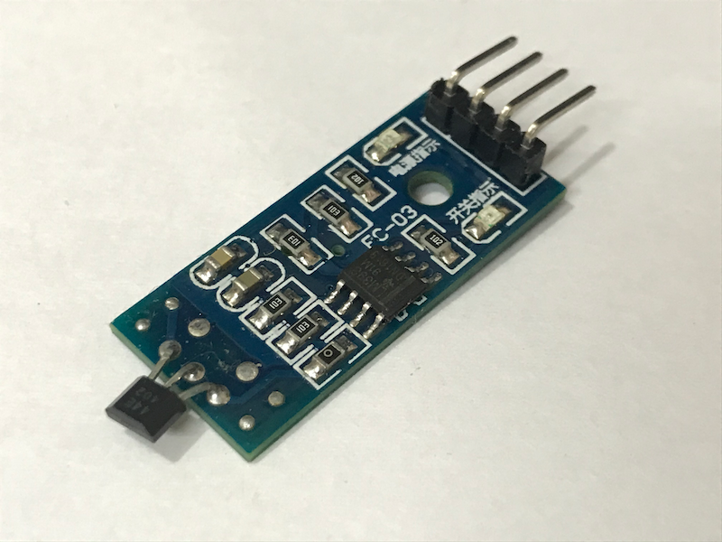
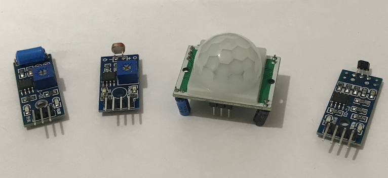
A Hall sensor can measure the strength of magnetic field. As its name suggested, this sensor uses the Hall effect to do its job. If you are interested in the physics behind it, you can take of look of this Wikipedia article.
This time, we are going to focus on how to use a digital Hall sensor with Arduino, i.e. a Hall sensor that can only tell us whether a magnet is present. There are analog version of Hall sensor which can measure the strength of magnetic field, but the digital one should be enough for most of our projects.
For this particular Hall sensor, when the magnetic field surrounding it is above its threshold, it will output a LOW signal (0V in Arduino); otherwise, it will output a HIGH signal (5V in Arduino). Therefore, when a magnet moves closer the sensor, the sensor will output a LOW signal. When a magnet moves alway from the sensor, the sensor will output a HIGH signal.
NOTE: Some Hall sensors may output signals in the exact opposite way! You should test the Hall sensor before you use it in your project.
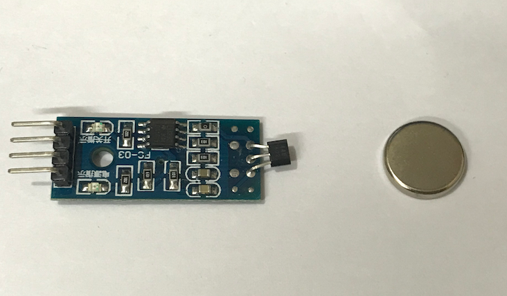
This simple mechanism has many applications. For example, a laptop usually has a small magnet at the edge of its lid and a Hall sensor near the keyboard. When the lid is closed, the Hall sensor detects the presence of the magnet. The, the computer knows the lid is closed and turns off the screen.

In this tutorial, we will:
- read the input from a digital Hall sensor
- use the input from a digital Hall sensor to control other devices
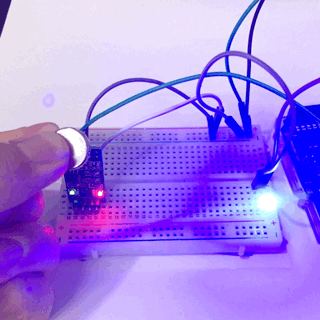
To achieve these learning outcomes, we will control an LED light by using a digital Hall sensor.
Materials and Tools
- Arduino Uno x 1
- Digital Hall sensor x 1
- LED x 1
- Breadboard x 1
- Male-to-male breadboard jumpers x 7
- Digital light sensor x 1 (for the assignment only)
1. Read the Input from the Sensor
Let’s connect the Hall sensor to the Arduino. There are three pins on the Hall sensor board: VCC, GND and DO.
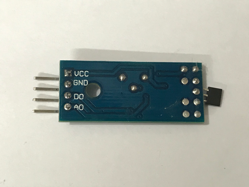
The VCC pin is for powering up the sensor, the GND pin should be connected to the ground and the DO pin will output the signals. With the help of a breadboard, connect the pins according to the following table.
| Hall sensor | Arduino |
|---|---|
| VCC | 5V |
| GND | GND |
| DO | Pin 2 |
Just like in the tutorial Arduino for Absolute Beginners, we use Pin 2 to detect the digital signal. The only difference is that the signal in this project is generated by the sensor itself rather than by inserting a wire or pushing a button. With this small difference in mind, let’s write the Arduino program to read the signal from the sensor.
void setup(){
    pinMode(2, INPUT);
    Serial.begin(9600);
}

void loop() {
  int hallSensorStatus = digitalRead(2);

  if (hallSensorStatus == LOW){
    Serial.println("Magnet is detected!");
  } else{
    Serial.println("Magnet is not here!");
  }

  delay(1000);
}
This looks almost the same as the simple digital input code! Let’s upload the code to the Arduino, and then open the Serial Monitor. Put a magnet near the sensor and see what happens to the Serial Monitor.
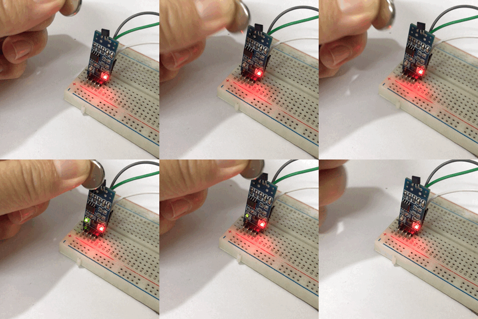
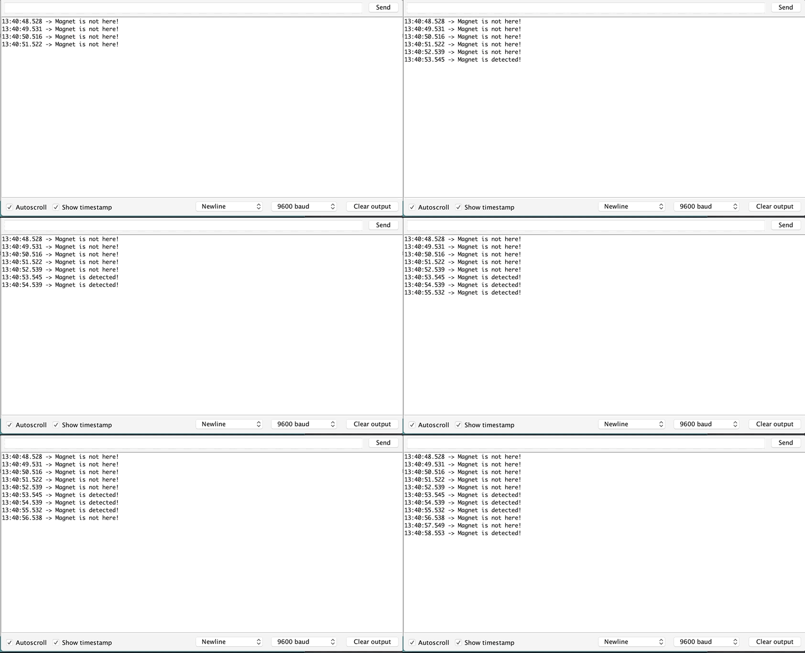
There are only two differences. The first one is in the setup function.
pinMode(2, INPUT);
Instead of INPUT_PULLUP for a push button, we use INPUT this time. Generally, you can use INPUT as long as the sensors always produce well-defined signals (0V or 5V in Arduino).
NOTE: For a push button, this is not the case. When a button is not pushed, the digital pin will be in a disconnected circuit and hence at an undetermined (floating) state, unless a pull-up or a pull-down resistor is used. Using
INPUT_PULLUPinstructs the Arduino to use its internal pull-up resistor. In this way, the pin will be in theHIGHstate when the button is not pushed. We will cover pull-up and pull-down resistors in more advanced tutorials.
The second difference is in the loop function:
if (hallSensorStatus== LOW){
    /* code to be executed  */
}
Since the Hall sensor outputs a HIGH signal, this if statement checks whether the read value from Pin 2 is equal to HIGH, and execute the codes enclosed by the parentheses following the condition.
If you find any difficulties, check out the model answer or ask us via our Facebook page.
2. Use the Hall Sensor to Control an LED
In the simple digital input/output project, we use a wire (or a button) to control an LED light. Let’s go ahead and do this again with the Hall sensor. Connect the LED to the Arduino as follows:
| LED | Arduino |
|---|---|
| Anode | Pin 13 |
| Cathode | GND |
Then, we modify the original program.
void setup() {
  pinMode(13, OUTPUT);
  pinMode(2, INPUT);
}

void loop() {
  int hallSensorStatus = digitalRead(2);

  if (hallSensorStatus == HIGH){
    digitalWrite(13, HIGH);
  } else{
    digitalWrite(13, LOW);
  }
}
As usual, a new line pinMode(13, OUTPUT); is added in the setup function so that Pin 13 can be used to control the LED. In the loop function, instead of printing some texts to the Serial Monitor, the LED is turned on or off according to the signal from the Hall sensor.
Upload the code to the Arduino, and you should be able to see the result!
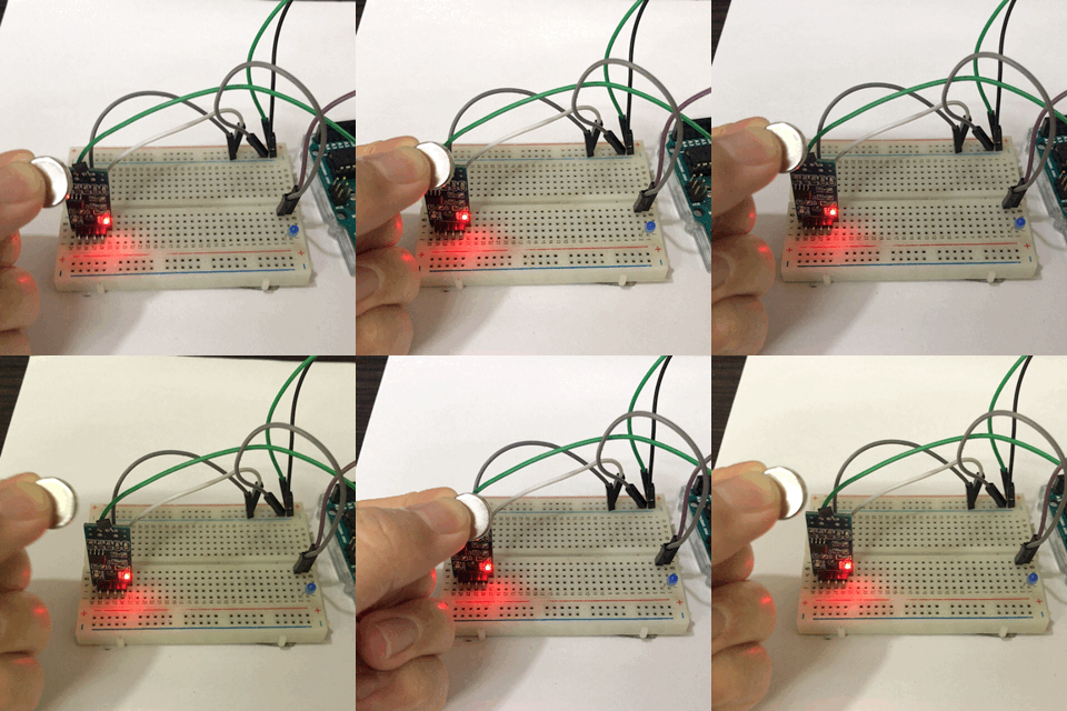
This exercise should be fairly straightforward. However, if you are new to this and find any difficulties, check out the model answer or ask us via our Facebook page.
3. Conclusion and Assignment
In this tutorial, we use a sensor which outputs digital signals to control an actuator. Essentially, we get data from the real world, process the data with a computer (microcontroller), and control other things according to the processing result. For novices, it’s important to master such concepts, as this is pretty much the basis of all software-controlled systems.
To consolidate the concepts, you can do the following practice with a digital light sensor.
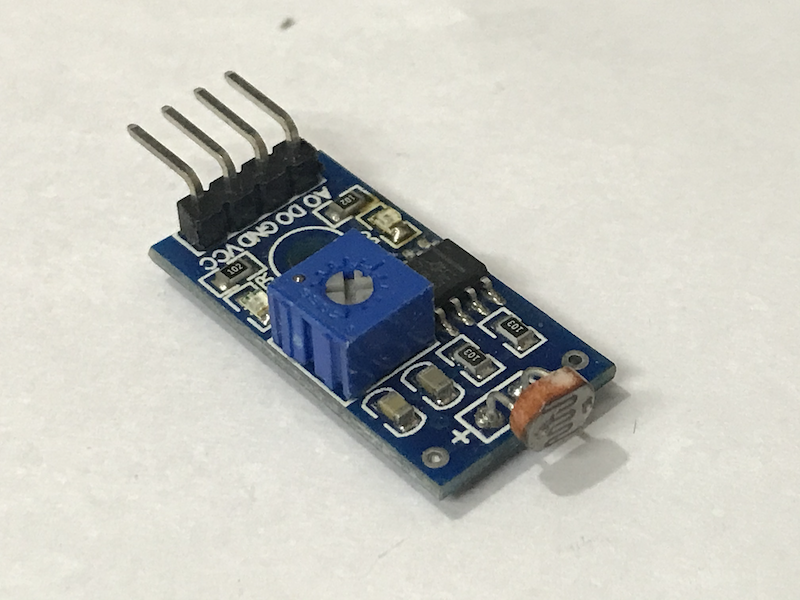
It’s basically a photoresistor with a breakout board. When the light level is higher than its threshold (which can be adjusted by moving the variable resistor on the board), it will output a HIGH signal; otherwise, it will output a LOW signal.
Use this light sensor to achieve the following:
When the light level is higher than a threshold, turn OFF the LED; otherwise, turn ON the LED.
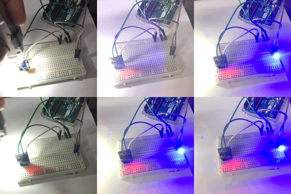
This is pretty similar to the automatic lighting system in a smart home. If you can master the skills of building this system, endless possibilities are waiting for you! So if you find any problems, check out the model answer to the assignment, or ask us via our Facebook page.