Introduction
In the previous tutorial, we run the new TensorFlow Lite object detection sample program on Raspberry Pi. In fact, we can modify this example and build our own object tracking camera. Specifically, we can achieve this with the following few steps:
- attach the camera to a mount that can be moved by a servo motor,
- use the object detection results from the example program to calculate the position of an object relative to the screen centre,
- move a servo motor according to the calculation result.
NOTE: Before you proceed, make sure you have installed all the necessary libraries and activate the correct virtual environment. If you haven’t done so, check out this tutorial for how you can do that.
Pan-tilt Camera Mount and Servo Motors
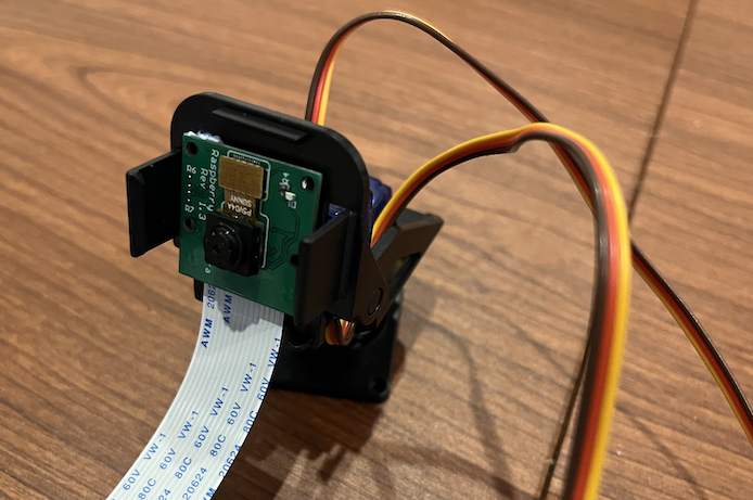
For simplicity, we will attach the camera to the pan-tilt kit from Adafruit. It comes with a camera mount and two servo motors. Therefore, for the hardware side, all we need to do is to connect the servo motors to the Raspberry Pi with a few jumper wires and attach the camera to the camera mount. Moreover, we will demonstrate how the pan motion can be controlled with the object detection program only. The part for the tilt motion is very similar and we leave it to you as an exercise.
Control a Servo Motor with Raspberry Pi
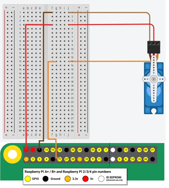
Controlling a servo motor with Raspberry Pi is quite similar to controlling it with an Arduino. First, we connect the servo motor to the GPIOs of the Raspberry Pi as follows.
| Servo | Raspberry Pi |
|---|---|
| VCC (red wire) | 5V |
| GND (brown wire) | GND |
| PWM signal (orange wire) | Pin 11 (GPIO17) |

Inside the folder ~/ai/examples/lite/examples/object_detection/raspberry_pi, create a new Python script file called servo.py. Put the following code inside the file:
# Import libraries
import RPi.GPIO as GPIO
import time

# Set GPIO numbering mode
GPIO.setmode(GPIO.BOARD)


class Servo():
    def __init__(self, pin, freq=50):
        self.pin = pin
        self.freq = freq
        self.started = False

    def start(self):
        GPIO.setup(self.pin, GPIO.OUT)
        self.output = GPIO.PWM(self.pin, self.freq)
        self.output.start(0)
        self.started = True
        print("Start sending signal to the servo.")

    def set_angle(self, angle):
        if not self.started:
            print('The servo has not started sending signal.')
            return
        if angle < 0 or angle > 180:
            raise ValueError('The angle must be between 0 and 180')
        self.output.ChangeDutyCycle(2+(angle/18))
        time.sleep(0.5)
        self.output.ChangeDutyCycle(0)

    def end(self):
        if self.started:
            self.started = False
            self.output.stop()
            GPIO.cleanup()
            print("Stop sending signal to the servo.")

    def __del__(self):
        self.end()


def main():
    try:
        # Set pin 11 as an output, and pulse 50Hz
        servo = Servo(11, 50)
        # Let the Raspberry Pi send signal to the servo motor
        servo.start()
        while True:
            try:
                # Ask user for angle and turn servo to it
                angle = float(input('Enter angle between 0 & 180: '))
                # Set the angle
                servo.set_angle(angle)
            except ValueError as e:
                print(e)
                continue
    except KeyboardInterrupt:
        # Press Ctrl+C to end the program
        print("End of program.")
    finally:
        # Cleanup at the end of the program
        if servo.started:
            servo.end()


if __name__ == "__main__":
    main()
You can execute the script servo.py by running the following command in the terminal:
(tfl) pi@raspberrypi:~/ai/examples/lite/examples/object_detection/raspberry_pi$ python servo.py
The program will ask you to enter a number from 0 to 180. The servo motor will turn to the specified position once you enter the number. We won’t go into the details of this script in this tutorial, but we recommand you to watch the following excellent video from ExplainingComputers to understand how this script actually works.
Modifying the Object Detection Program
Inside the folder ~/ai/examples/lite/examples/object_detection/raspberry_pi, there are other .py files other than the detect.py that we executed in the last tutorial and the servo.py that we just wrote. In particular, the file utils.py contains functions that handle the object detection results. We only need to modify this file for making our object tracking camera.
The strategy of moving the camera is simple. We just compare the centre of the bounding box of the target object with the image centre and determine, and move the servo motors such that the difference between these two centres can be reduced. In other words, the movement can be determined by the vector from the bounding box centre to the image centre. Both of these centres can be found in the visualize function inside utils.py. Therefore, if we add some codes to find the coordinates of these centres, calculate the vector and use this vector to move the servo in visualize, our object tracking project is basically done.
Before we modify visualize, we need to add some codes in utils.py.
First, we import the Servo class that we wrote earlier as well as the time library.
from servo import Servo
import time
Then, we set up the servo motor by creating an object of the Servo class. After the initialisation, we set the servo position to 90 degree as its initial centred position.
Then, we define two variables pan_angle and move_threshold. The pan_angle variable stores the current position of the pan servo and the x_move_threshold stores the minimum difference between the x-coordinate of the bounding box centre and that of the image centre that can trigger a movement.
pan_angle = 90
x_move_threshold = 50
Afterwards, we define the function move that moves the servo motor according to the vector from the bounding box centre to the image centre. The function itself is self-explanatory.
def move(vector):
  global pan_angle, pan_servo
  if abs(vector[0]) > x_move_threshold:
    if vector[0] < 0:       # object is on the right of the screen
      pan_angle += 5        # move the camera in the anticlockwise direction, i.e. increase the servo angle
    else:                   # object is on the left of the screen
      pan_angle -= 5        # move the camera in the clockwise direction, i.e. reduce the servo angle

    # Make sure that the angle is within 0 to 180
    if pan_angle < 0:
      pan_angle = 0
    if pan_angle > 180:
      pan_angle = 180
    pan_servo.set_angle(pan_angle)

    # The tilt angle can be set in the same way with vector[1]s

    # The servo needs some time to move
    time.sleep(1)
NOTE: If you use the PiCamera module to capture the image, the image is horizontally flipped and you may need to adjust the direction of movement accordingly.
Now, we can modify the visualize function. Before the line return image, add the following codes.
if (class_name == 'bottle' and probability > 0.5):
    image_centre = (image.shape[1]/2, image.shape[0]/2)
    xmin, xmax, ymin, ymax = detection.bounding_box.left, detection.bounding_box.right, detection.bounding_box.top, detection.bounding_box.bottom
    bounding_box_centre = ((xmin+xmax)/2, (ymin+ymax)/2)
    vector = np.array(image_centre) - np.array(bounding_box_centre)
    move(vector)
Let’s take a look of them in details. First of all, we need to decide what object we want to track and the detection sensitivity. We can use the class_name and probability variable to construct the condition we want. For instance, we can move the camera when a bottle is detected and the probability is over 0.5 (50%).
if (class_name == 'bottle' and probability > 0.5):
Then, we can calculate the image centre.
image_centre = (image.shape[1]/2, image.shape[0]/2)
Similarly, we calculate the bounding box centre of the target object.
    xmin, xmax, ymin, ymax = detection.bounding_box.left, detection.bounding_box.right, detection.bounding_box.top, detection.bounding_box.bottom
    bounding_box_centre = ((xmin+xmax)/2, (ymin+ymax)/2)
With the two centres, we can calculate the vector we need.
vector = np.array(image_centre) - np.array(bounding_box_centre)
Finally, we call the move function that we wrote to move the servo.
move(vector)
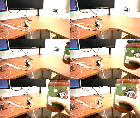
After the modification, we can run detect.py (make sure that the virtual environment with all the necessary libraries has been activated) and the camera will track the target object!

The sample code for this project can be found here.