Introduction
In a typical robot, there are usually a few movable parts. For example, a robotic arm may need to move in a particular direction and grab something. Such maneuvers require a high degree of precision, and a simple DC motor is not suitable for such tasks. Instead, servo motors are needed. Luckily, hobbyist servo motors are inexpensive and small. Perhaps more importantly, it is very easy to use an Arduino to control these small servo motors.
In this tutorial, we will learn:
- what is servo motor is,
- how to use an Arduino to control a servo motor
To achieve the above learning outcomes, we will build a simple gift box that can be opened an closed by a servo motor.
Materials and Tools
- Arduino Uno x 1
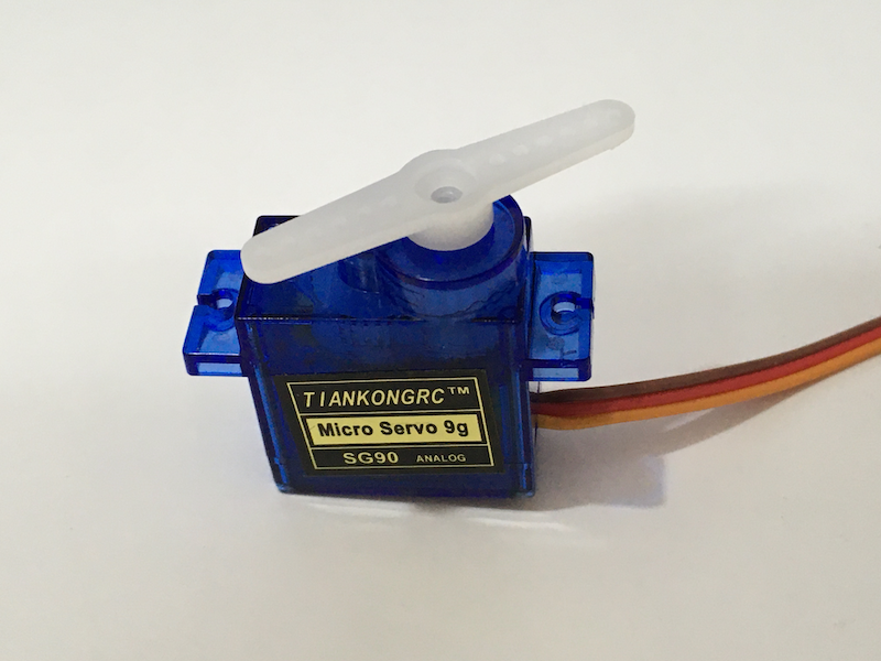
- SG90 servo motor x 1
- Jumper wires
- Paper box x 1
Servo Motor
If you look at a servo motor closely, you will find that it actually has a DC motor inside. There is also a gear box attached to the motor.
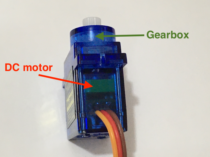
Through gearing, the rotation speed is lowered, and the output torque is increased. Other than the gear box, there is also a controlling circuit inside a servo motor. To understand more about how a servo motor works, you may read this nice article from ScienceBuddies. We will focus on controlling a servo motor instead.
Positional rotation servo
This time, we focus on positional servos. The shaft of this type of servo motors can typically rotate 180 degrees.
The angle position is controlled by a pulse-width-modulation (PWM) signal. For instance, to control the servo motor we use in this tutorial, the SG90, we need to use 50 Hz PWM signal (i.e. the period is 20 ms) to control the servo motor. The angle position is controlled by the duty cycle of the PWM signal. The shaft of the SG90 will rotate to the following positions according to different values of duty cycle:
| Angle position | Duty cycle (50 Hz PWM) |
|---|---|
| 0 degree | 5% (1 ms “on”) |
| 90 degree | 7.5% (1.5 ms “on”) |
| 180 degree | 10% (2 ms “on”) |
This is kind of messy. Luckily, the servo library of Arduino enables us to handle all of these with a few simple function calls.
Control the Servo with Arduino
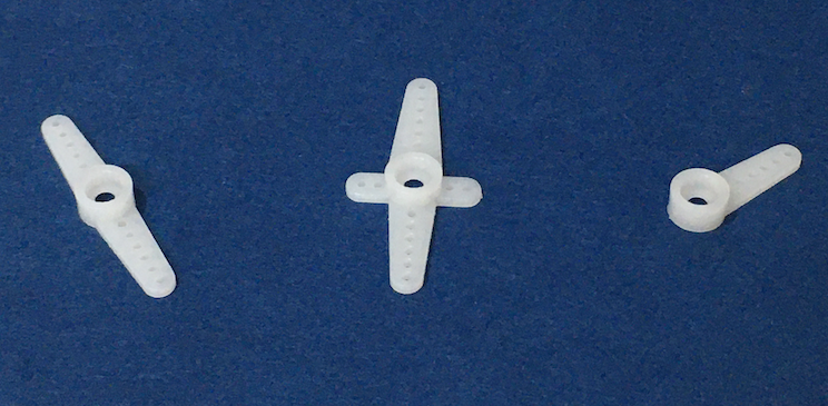
First, let’s attach a shaft to the servo motor. The SG90 comes with different shafts, so you can choose the most suitable one for your projects.
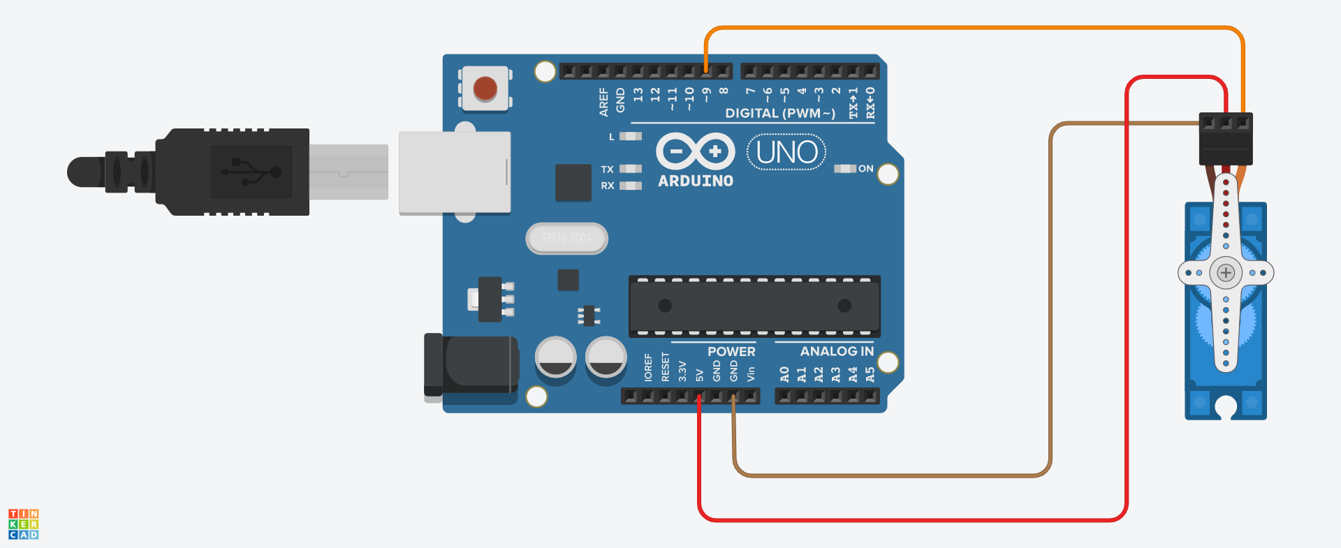
Then, we need to connect the servo to the Arduino. The servo motor only has three cables: power (usually in red), ground (usually in brown) and signal (usually in orange). Connect the cables to the Arduino as follows.
| Servo motor | Arduino |
|---|---|
| Power | 5V |
| Ground | GND |
| Signal | Pin 9 |
Then, we write a simple Arduino program to control the servo motor.
#include <Servo.h>
Servo myservo;

void setup(){
    myservo.attach(9);
}

void loop(){
    myservo.write(0);
    delay(2000);
    myservo.write(90);
    delay(2000);
}
Upload the program to the Arduino, and the servo motor should move to the 0 degree and the 90 degree positions repeatedly.
Let’s look at the codes in details.
To use the servo motor library, we need to import the library with the #include preprocessor macro.
#include <Servo.h>
Then, we create an object representing the servo motor. Declaring an object of a class is just like declaring a variable.
Servo myservo;
An object of the Servo class has the necessary data structures and functions for controlling the servo motor.
NOTE: Object is an important concept of programming. Object oriented programming (OOP) is a paradigm used by many programming languages. You may refer to this W3Schools tutorial about OOP to know more about it.
In the setup function, we assign a pin for sending the PWM signal to the servo motor by calling the attach function of the myservo object.
void setup(){
    myservo.attach(9);
}
NOTE: Although we use the PWM-capable pin 9 in the example, the servo library can be used with any digital output pin. That’s because the PWM frequency is just 50 Hz, and the Arduino can create the signal via bit-banging.
In the loop function, we simply call the write function of the myservo object to move the servo motor to a particular angle position.
void loop(){
    myservo.write(0); // from 0 to 180
    // ... some other codes
}
The parameter of this function is the angle position, ranging from 0 to 180. Feel free to enter other values and see how the shaft moves. If you find any difficulties, you may check out the sample code here.
Attach the Servo to a Box
Let’s use the servo motor to open and close the lid of a paper box. Remove the servo motor from the Arduino, and following the steps below.
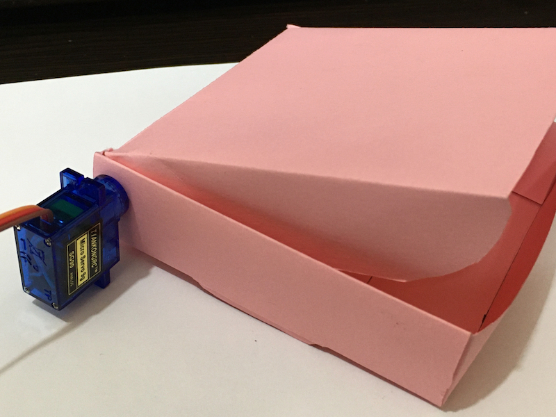
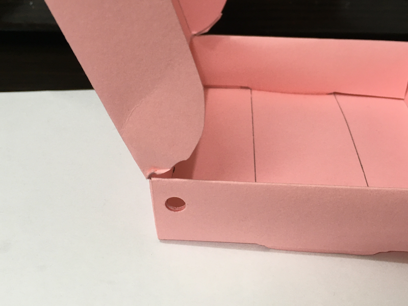
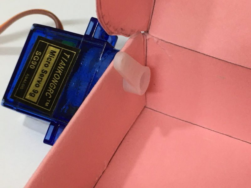
First, we make a hole near the hinge of the lid on a face of the box:
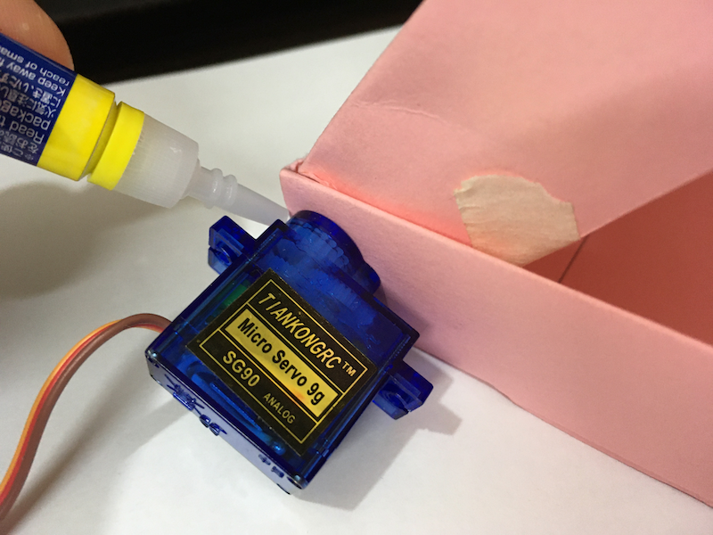
Then, put the top gear of the servo motor into the hole, and use glue to fix the servo motor to the box:

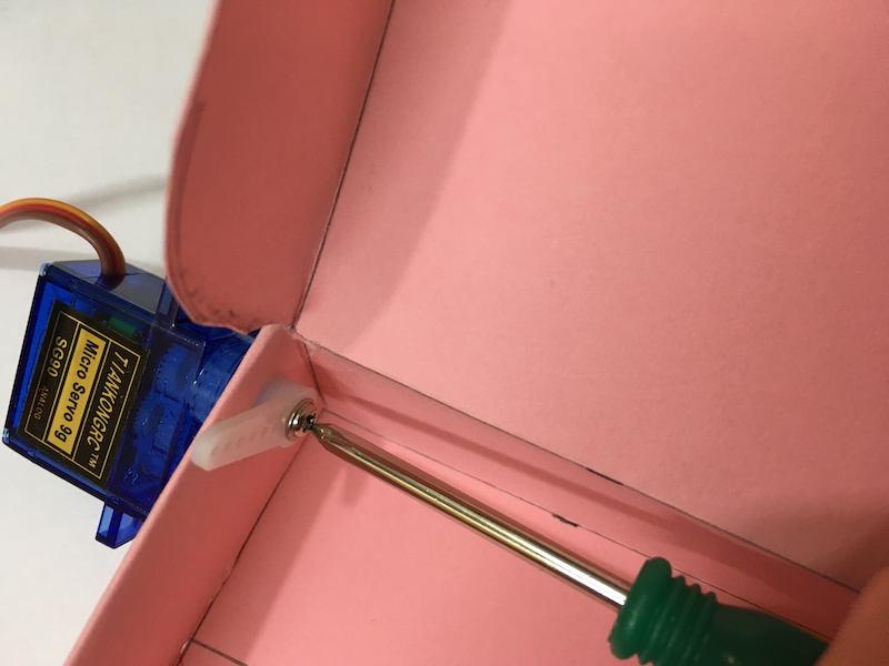
Next, we attach the shaft with one arm to the servo motor, and use a screw to fix the shaft.
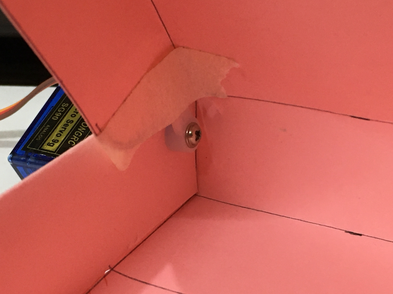
Finally, we fix the shaft to the lid of the box with tape or glue.
Attach the servo motor to the Arduino again. The box can be opened and closed by the servo motor!

Conclusion and Assignment
Being able to control a servo motor with an Arduino is a huge step towards robotics. You may 3D print/laser cut a robotic arm like this one and use servo motors to drive the arm. With designs like the slider crank mechanism, you may even convert rotational motion into linear motion. There are just endless possibilities of projects based on servo motors.
To consolidate the knowledge, you may try the following assignment:
Use a potentiometer to control a servo that opens and closes the lid of the box.
Here’s the circuit diagram for your reference:
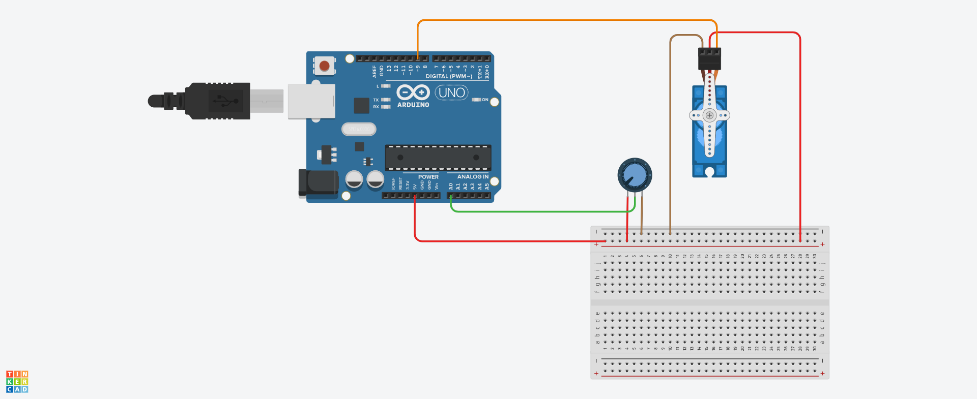
You may look at the sample code here. If you find any difficulties, you may also ask us via our Facebook page.